Quantcast
Channel: CCNA Training
Viewing all 515 articles
Browse latest View live

CCNA – EIGRP Questions

$
0
0

Here you will find answers to EIGRP Questions

Note: If you are not sure about EIGRP, please read my EIGRP tutorial
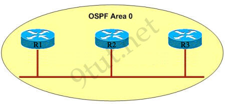
Question 1

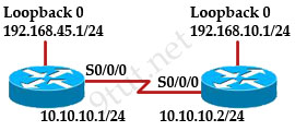
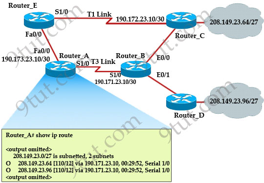
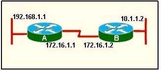
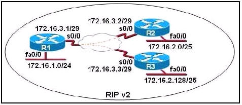
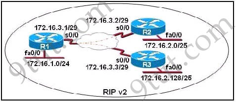
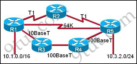
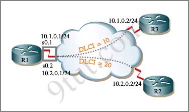
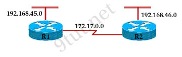
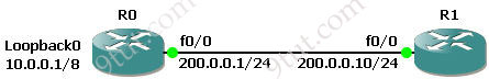
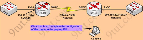
Refer to the exhibit, when running EIGRP what is required for R1 to exchange routing updates with R3?

EIGRP_AS_number

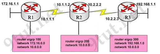
A – AS numbers must be changed to match on all the routers
B – Loopback interfaces must be configured so a DR is elected
C – The no auto-summary command is needed on R1 and R3
D – R2 needs to have two network statements, one for each connected network


Answer: A

Question 2:

As a Cisco technician, you need to know EIGRP protocol very well. Which of the following is true about EIGRP successor routes? (Choose two)

A – A successor route is used by EIGRP to forward traffic to a destination
B – Successor routes are stored in the neighbor table following the discovery process
C – Successor routes are flagged as “active” in the routing table
D – A successor route may be backed up by a feasible successor route
E – Successor routes are stored in the neighbor table following the discovery process.


Answer: A D

Explanation:

B is not correct because neighbor table only contains a list of directly connected EIGRP routers that have an adjacency with this router, it doesn’t contain successor routes.

C is not correct because successor routes are not flagged as “active”, they are always the best route to reach remote networks and are always used to send packets.

A and D are correct because successor route is the best and primary route to a remote network. It is stored in the routing table and topology table. If this route fails, a backup route (called feasible successor route) in the topology table will be used to route traffic to a destination.

Question 3:

Which two statements are true regarding EIGRP? (Choose two)

A – Passive routes are in the process of being calculated by DUAL
B – EIGRP supports VLSM, route summarization, and routing update authentication
C – EIGRP exchanges full routing table information with neighboring routers with every update
D – If the feasible successor has a higher advertised distance than the successor route, it becomes the primary route
E – A query process is used to discover a replacement for a failed route if a feasible successor is not identified from the current routing information


Answer: B E

Explanation:

Diffusing Update Algorithm (DUAL) is the algorithm for selecting and maintaining the best path to each remote network. DUAL tracks all the routes advertised by neighbors and selects routes based on feasible successors. It inserts lowest cost paths into the routing table (these routes are known as primary routes or successor routes) -> A is not correct.

EIGRP is still a distance-vector protocol, but has certain features that belong to link-state algorithms (like OSPF) than distance-vector algorithms. For example, EIGRP sends a partial routing table update, which includes just routes that have been changed, not the full routing table like distance-vector algorithms -> C is not correct.

The feasible successor route will become the primary route when its advertised distance is lower than the feasible distance of the successor route. The feasible successor route can be used in the event that the successor route goes down. Notice that the feasible successor route does not get installed in the routing table but is kept in the topology table as a backup route -> D is not correct.

“Support VLSM, route summarization, and routing update authentication” are the features of EIGRP -> B is correct.

When a route fails and has no feasible successor, EIGRP uses a distributed algorithm called Diffusing Update Algorithm (DUAL) to discover a replacement for a failed route. When a new route is found, DUAL adds it to the routing table -> E is correct.

Question 4

Which type of EIGRP route entry describes a feasible successor?

A. a primary route,stored in the routing table
B. a backup route,stored in the routing table
C. a backup route,stored in the topology table
D. a primary route,stored in the topology table


Answer: C

Explanation

Feasible successor is a route whose Advertised Distance is less than the Feasible Distance of the current best path. A feasible successor is a backup route, which is not stored in the routing table but stored in the topology table.

Question 5

Refer to the exhibit. Given the output from the show ip eigrp topology command, which router is the feasible successor?

router# show ip eigrp topology 10.0.0.5 255.255.255.255
IP-EIGRP topology entry for 10.0.0.5/32 State is Passive, Query
origin flag is 1, 1 Successor(s), FD is 41152000

A.

10.1.0.1 (Serial0), from 10.1.0.1, Send flag is 0×0
Composite metric is (46152000/41640000), Route is Internal
Vector metric:
Minimum bandwidth is 64 Kbit
Total delay is 45000 Microseconds
Reliability is 255/255
Load is 1/255
Minimum MTU is 1500
Hop count is 2

B.

10.0.0.2 (Serial0.1), from 10.0.0.2, Send flag is 0×0
Composite metric is (53973248/128256), Route is Internal
Vector Metric:
Minimum bandwidth is 48 Kbit
Total delay is 25000 Microseconds
Reliability is 255/255
Load is 1/255
Minimum MTU is 1500
Hop count is 1

C.

10.1.0.3 (Serial0), from 10.1.0.3, Send flag is 0×0
Composite metric is (46866176/46354176), Route is Internal
Vector metric:
Minimum bandwidth is 56 Kbit
Total delay is 45000 microseconds
Reliability is 255/255
Load is 1/255
Minimum MTU is 1500
Hop count is 2

D.

10.1.1.1 (Serial0.1), from 10.1.1.1, Send flag is 0×0
Composite metric is (46763776/46251776), Route is External
Vector metric:
Minimum bandwidth is 56 Kbit
Total delay is 41000 microseconds
Reliability is 255/255
Load is 1/255
Minimum MTU is 1500
Hop count is 2


Answer: B

Explanation

To be the feasible successor, the Advertised Distance (AD) of that route must be less than the Feasible Distance (FD) of the successor. From the output of the “show ip eigrp topology 10.0.0.5 255.255.255.255″ we learn that the FD of the successor is 41152000.

Now we will mention about the answers, in the “Composite metric is (…/…)” statement the first parameter is the FD while the second parameter is the AD of that route. So we need to find out which route has the second parameter (AD) less than 41152000 -> only answer B satisfies this requirement with an AD of 128256.

Question 6

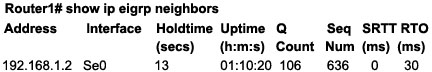
A network administrator is troubleshooting an EIGRP problem on a router and needs to confirm the IP addresses of the devices with which the router has established adjacency. The retransmit interval and the queue counts for the adjacent routers also need to be checked. What command will display the required information?

A. Router# show ip eigrp adjacency
B. Router# show ip eigrp topology
C. Router#show ip eigrp interfaces
D. Router#show ip eigrp neighbors


Answer: D

Explanation

Below is an example of the show ip eigrp neighbors command. The retransmit interval (Smooth Round Trip Timer – SRTT) and the queue counts (Q count, which shows the number of queued EIGRP packets) for the adjacent routers are listed:

EIGRP_show_ip_eigrp_neighbors_command.jpg

Question 7

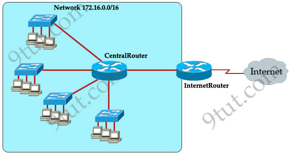
Refer to the exhibit. How many paths can the EIGRP routing process use to forward packets from HQ_Router to a neighbor router?

HQ_Router# show ip protocols
Routing Protocol is “eigrp 109″
Outgoing update filter list for all interfaces is not set
Incoming update filter list for all interfaces is not set
Default networks flagged in outgoing updates
Default networks accepted from incoming updates
EIGRP metric weight K1=1, K2=0, K3=1, K4=0, K5=0
EIGRP maximum hopcount 100
EIGRP maximum metric variance 3
Redistributing: eigrp 109
EIGRP NSF-aware route hold timer is 240s
Automatic network summarization is not in effect
Maximum path: 4
Routing for Networks:
20.10.10.0/24
172.30.10.0/24
192.168.1.0
Routing Information Sources:
Gateway Distance Last Update
20.10.10.2 90 00:13:12
172.30.10.2 90 01:13:06
Distance: internal 90 external 170
HQ_Router#

A. two equal-cost paths
B. two unequal-cost paths
C. three equal-cost paths
D. three unequal-cost paths
E. four equal-cost paths
F. four unequal-cost paths


Answer: F

Explanation

The “Maximum path: 4″ means EIGRP can use up to 4 equal-cost paths to forward packets from HQ_Router to a neighbor router. But here the variance is set to 3 which allows unequal-cost paths. Therefore in this case EIGRP can use up to four unequal-cost paths.

Question 8

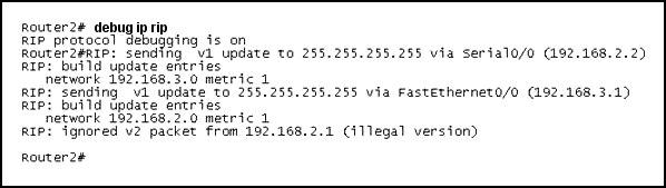
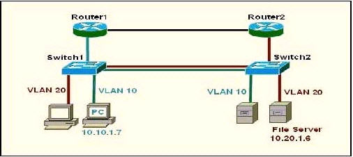
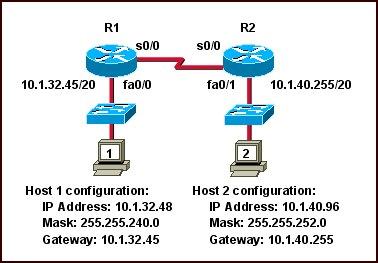
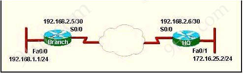
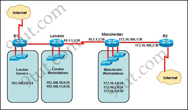
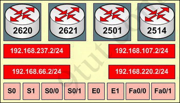
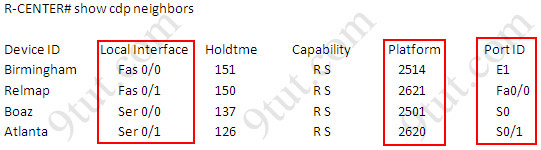
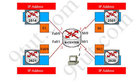
IP address and routing for the network are configured as shown in the exhibit. The network administrator issues the show ip eigrp neighbors command from Router1 and receives the output shown below the topology. Which statement is true?

EIGRP_show_ip_eigrp_neighbors.jpg

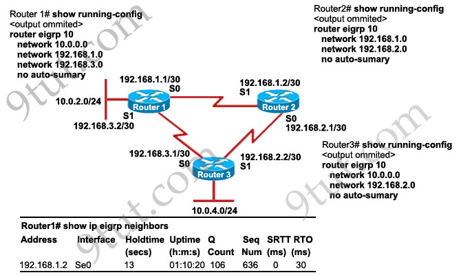
A. It is normal for Router1 to show one active neighbor at a time to prevent routing loops.
B. Routing is not completely configured on Router3.
C. The IP addresses are not configured properly on the Router1 and Router3 interfaces.
D. The no auto-summary command configured on the routers prevents Router1 and Router2 from forming a neighbor relationship.


Answer: B

Explanation

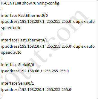
From the output of Router1, we learn that Router1 has not established neighborship with R3 yet. Also from the “show running-config” on Router3 we notice that the “network 192.168.3.0″ statement is missing -> the configuration on Router3 is not complete.


CCNA – OSPF Questions 2

$
0
0

Here you will find answers to OSPF Questions – Part 2

Note: If you are not sure about OSPF, please read my OSPF tutorial

Question 1

Refer to the exhibit. Which two statements are true about the loopback address that is configured on RouterB? (Choose two)

OSPF_loopback.jpg

A. It ensures that data will be forwarded by RouterB.
B. It provides stability for the OSPF process on RouterB.
C. It specifies that the router ID for RouterB should be 10.0.0.1.
D. It decreases the metric for routes that are advertised from RouterB.
E. It indicates that RouterB should be elected the DR for the LAN.


Answer: B C

Explanation

A loopback interface never comes down even if the link is broken so it provides stability for the OSPF process (for example we use that loopback interface as the router-id) -> B is correct.

The router-ID is chosen in the order below:

+ The highest IP address assigned to a loopback (logical) interface.
+ If a loopback interface is not defined, the highest IP address of all active router’s physical interfaces will be chosen.

-> The loopback interface will be chosen as the router ID of RouterB -> C is correct.

Question 2

Which characteristics are representative of a link-state routing protocol? (Choose three)

A. provides common view of entire topology
B. exchanges routing tables with neighbors
C. calculates shortest path
D. utilizes event-triggered updates
E. utilizes frequent periodic updates


Answer: A C D

Explanation

Each of routers running link-state routing protocol learns paths to all the destinations in its “area” so we can say A is correct although it is a bit unclear.

Link-state routing protocols generate routing updates only (not the whole routing table) when a change occurs in the network topology so B is not correct.

Link-state routing protocol like OSPF uses Dijkstra algorithm to calculate the shortest path -> C is correct.

Unlike Distance vector routing protocol (which utilizes frequent periodic updates), link-state routing protocol utilizes event-triggered updates (only sends update when a change occurs) -> D is correct but E is not correct.

Question 3

OSPF_DR_elect.jpg

The internetwork infrastructure of company XYZ consists of a single OSPF area as shown in the graphic. There is concern that a lack of router resources is impeding internetwork performance.

As part of examining the router resources the OSPF DRs need to be known.

All the router OSPF priorities are at the default and the router IDs are shown with each router.

Which routers are likely to have been elected as DR? (Choose two)

A. Corp-1
B. Corp-2
C. Corp-3
D. Corp4
E. Branch-1
F. Branch-2


Answer: D F

Explanation

There are 2 segments on the topology above which are separated by Corp-3 router. Each segment will have a DR so we have 2 DRs.

To select which router will become DR they will compare their router-IDs. The router with highest (best) router-ID will become DR. The router-ID is chosen in the order below:

+ The highest IP address assigned to a loopback (logical) interface.

+ If a loopback interface is not defined, the highest IP address of all active router’s physical interfaces will be chosen.

In this question, the IP addresses of loopback interfaces are not mentioned so we will consider IP addresses of all active router’s physical interfaces. Router Corp-4 (10.1.40.40) & Branch-2 (10.2.20.20) have highest “active” IP addresses so they will become DRs.

Question 4

OSPF_show_ip_interface_brief.jpg

A network associate has configured OSPF with the command:
City(config-router)# network 192.168.12.64 0.0.0.63 area 0

After completing the configuration, the associate discovers that not all the interfaces are participating in OSPF.
Which three of the interfaces shown in the exhibit will participate in OSPF according to this configuration statement? (Choose three)

A. FastEthernet0/0
B. FastEthernet0/1
C. Serial0/0
D. Serial0/1.102
E. Serial0/1.103
F. Serial0/1.104

Answer: B C D

Explanation

The “network 192.168.12.64 0.0.0.63″ equals to network 192.168.12.64/26. This network has:
+ Increment: 64 (/26= 1111 1111.1111 1111.1111 1111.1100 0000)
+ Network address: 192.168.12.64
+ Broadcast address: 192.168.12.127
Therefore all interface in the range of this network will join OSPF -> B C D are correct.

Question 5

When running OSPF, what would cause router A not to form an adjacency with router B?

OSPF_adjacency.jpg

A. The loopback addresses are on different subnets.
B. The values of the dead timers on the routers are different.
C. Route summarization is enabled on both routers.
D. The process identifier on router A is different than the process identifier on router

Answer: B

Explanation

To form an adjacency (become neighbor), router A & B must have the same Hello interval, Dead interval and AREA number.

Question 6

Refer to the exhibit. The network is converged. After link-state advertisements are received from Router_A, what information will Router_E contain in its routing table for the subnets 208.149.23.64 and 208.149.23.96?

OSPF_routing_table.jpg

A. 208.149.23.64[110/13] via 190.173.23.10, 00:00:00:07, FastEthernet0/0
208.149.23.96[110/13] via 190.173.23.10, 00:00:00:16, FastEthernet0/0

B. 208.149.23.64[110/1] via 190.173.23.10, 00:00:00:07, Serial1/0
208.149.23.96[110/3] via 190.173.23.10, 00:00:00:16, FastEthernet0/0

C. 208.149.23.64[110/13] via 190.173.23.10, 00:00:00:07, Serial1/0
208.149.23.96[110/13] via 190.173.23.10, 00:00:00:16, Serial1/0
208.149.23.96[110/13] via 190.173.23.10, 00:00:00:16, FastEthernet0/0

D. 208.149.23.64[110/13] via 190.173.23.10, 00:00:00:07, Serial1/0
208.149.23.96[110/13] via 190.173.23.10, 00:00:00:16, Serial1/0


Answer: A

Explanation

Router_E learns two subnets subnets 208.149.23.64 and 208.149.23.96 via Router_A through FastEthernet interface. The interface cost is calculated with the formula 108 / Bandwidth. For FastEthernet it is 108 / 100 Mbps = 108 / 100,000,000 = 1. Therefore the cost is 12 (learned from Router_A) + 1 = 13 for both subnets -> B is not correct.

The cost through T1 link is much higher than through T3 link (T1 cost = 108 / 1.544 Mbps = 64; T3 cost = 108 / 45 Mbps = 2) so surely OSPF will choose the path through T3 link -> Router_E will choose the path from Router_A through FastEthernet0/0, not Serial1/0 -> C & D are not correct.

In fact, we can quickly eliminate answers B, C and D because they contain at least one subnet learned from Serial1/0 -> they are surely incorrect.

Question 7

Refer to the exhibit. Given the output for this command, if the router ID has not been manually set, what router ID will OSPF use for this RouterD?

RouterD# show ip interface brief

show_ip_interface_brief.jpg


A. 10.1.1.2
B. 10.154.154.1
C. 172.16.5.1
D. 192.168.5.316


Answer: C

Explanation

The highest IP address of all loopback interfaces will be chosen -> Loopback 0 will be chosen as the router ID.

Question 8

Which commands are required to properly configure a router to run OSPF and to add network 192.168.16.0/24 to OSPF area 0? (choose two)

A. Router(config)#router ospf 1
B. Router(config)#router ospf 0
C. Router(config)#router ospf area 0
D. Router(config-router)#network 192.168.16.0 0.0.0.255 area 0
E. Router(config-router)#network 192.168.16.0 0.0.0.255 0
F. Router(config-router)#network 192.168.16.0 255.255.255.0 area 0


Answer: A D

Explanation

In the router ospf

command, theranges from 1 to 65535 so o is an invalid number -> A is correct but B is not correct.

To configure OSPF, we need a wildcard in the “network” statement, not a subnet mask. We also need to assgin an area to this process -> D is correct.

Question 9

Which parameter or parameters are used to calculate OSPF cost in Cisco routers?

A. Bandwidth, Delay and MTU
B. Bandwidth
C. Bandwidth and MTU
D. Bandwidth, MTU, Reliability, Delay and Load


Answer: B

The well-known formula to calculate OSPF cost is

Cost = 108 / Bandwidth

so B is the correct answer.

Question 10

Refer to the exhibit. Why are two OSPF designated routers identified on Core-Router?

Neighbor_ID Pri State Dead Time Address Interface
208.149.23.194 1 Full/DR 00:00:33 190.172.32.10 Ethernet1
208.149.23.60 1 Full/BDR 00:00:33 190.172.32.10 Ethernet0
208.149.23.130 1 Full/DR 00:00:39 190.172.32.10 Ethernet0

A. Core-Router is connected more than one multi-access network
B. The router at 208.149.23.130 is a secondary DR in case the primary fails.
C. Two router IDs have the same OSPF priority and are therefore tied for DR election
D. The DR election is still underway and there are two contenders for the role.


Answer: A

Explanation

OSPF elects one DR per multi-access network. In the exhibit there are two DR so there must have more than one multi-access network.

Question 11

What is the default maximum number of equal-cost paths that can be placed into the routing of a Cisco OSPF router?

A. 16
B. 2
C. unlimited
D. 4


Answer: D

Explanation

The default number of equal-cost paths that can be placed into the routing of a Cisco OSPF router is 4. We can change this default value by using “maximum-paths” command:

Router(config-router)#maximum-paths 2

Note: Cisco routers support up to 16 equal-cost paths. In detail, the default number of maximum paths is 32 for Cisco CRS-1 routers and 16 for Cisco XR 12000 Series Routers. The range is from 1 to 32 for Cisco CRS-1 routers and 1 to 16 for Cisco XR 12000 Series Routers.

(Reference: http://www.cisco.com/en/US/docs/ios_xr_sw/iosxr_r3.7/routing/configuration/guide/rc37ospf.html)


Question 12

What is the OSPF default frequency, in seconds, at which a Cisco router sends hello packets on a multiaccess network?

A. 10
B. 40
C. 30
D. 20


Answer: A

Explanation

On broadcast multiacess and point-to-point links, the default is 10 seconds. On NBMA, the default is 30 seconds.

Question 13

What is the default administrative distance of OSPF?
A. 120
B. 100
C. 90
D. 110


Answer: D

Question 14

What information does a router running a link-state protocol use to build and maintain its topological database? (Choose two)

A. hello packets
B. SAP messages sent by other routers
C. LSAs from other routers
D. beacons received on point-to-point links
E. routing tables received from other link-state routers
F. TTL packets from designated routers


Answer: A C

CCNA – OSPF Questions

$
0
0

Here you will find answers to OSPF Questions

Note: If you are not sure about OSPF, please read my OSPF tutorial

Question 1

Which of the following statements below best describe the process identifier that is used to run OSPF on a router? (Choose two)

A – It is an optional parameter required only if multiple OSPF processes are running on the router
B – It is locally significant
C – It is needed to identify a unique instance of an OSPF database
D – All routers in the same OSPF area must have the same process ID if they are to exchange routing information


Answer: B C

Question 2:

Why R1 can’t establish an OSPF neighbor relationship with R3 according to the following graphic? (Choose two)

OSPFneighbor

A – Configure EIGRP on these routers with a lower administrative distance
B – All routers should be configured for backbone Area 1
C – R1 and R3 have been configured in different areas
D – The hello and dead interval timers are not configured the same values on R1 and R3


Answer: C D

Explanation:

A is not correct because configure EIGRP on these routers (with a lower administrative distance) will force these routers to run EIGRP, not OSPF.

B is not correct because the backbone area of OSPF is always Area 0.

C and D are correct because these entries must match on neighboring routers:

- Hello and dead intervals
Area ID (Area 0 in this case)
– Authentication password
– Stub area flag

Question 3:

Which items are correct about the routing protocol OSPF? (Choose three)

A – Support VLSM
B – Increase routing overhead on the network
C – Confine network instability to one area of the network
D – Allow extensive control of routing updates


Answer: A C D

Explanation:

Routing overhead is the amount of information needed to describe the changes in a dynamic network topology. All routers in an OSPF area have identical copies of the topology database and the topology database of one area is hidden from the rest of the areas to reduce routing overhead because fewer routing updates are sent and smaller routing trees are computed and maintained (allow extensive control of routing updates and confine network instability to one area of the network).

Question 4:

Which three features are of OSPF routing protocol? (Choose three)

A – Converge quickly
B – OSPF is a classful routing protocol
C – Identify the best route by use of cost
D – Before exchanging routing information, OSPF routers find out neighbors


Answer: A C D

Question 5:

OSPF routing uses the concept of areas. What are the characteristics of OSPF areas? (Chose three)

A – Each OSPF area requires a loopback interface to be configured
B – Areas may be assigned any number from 0 to 65535
C – Area 0 is called the backbone area
D – Hierarchical OSPF networks do not require multiple areas
E – Multiple OSPF areas must connect to area 0
F – Single area OSPF networks must be configured in area 1


Answer: B C E

Explanation:

I used to think the answers should be C D E and here is my explanation:

OSPF can use an active interface for its router ID, so a loopback interface is not a must -> A is incorrect.

OSPF Area is a 32-bit number so we can use up to 232 – 1 = 4294967296 – 1 (since Area 0 is the first area). Remember that only process ID is a 16-bit number and ranges from 1 to 65535 -> B is incorrect.

F is incorrect too because single area OSPF netwoks must be configured in Area 0, which is called the backbone area.

For answer D, it is a bit hard to guess what they want to say about “hierarchical” but we should understand “Hierarchical OSPF networks” as “OSPF networks”. D is correct bercause we can only have one area (area 0 – the backbone area) for our networks.

But TT commented on 01-11-2010:

Especially to note on choice B, D, and E:

Choice B: we all know that The areas can be any number from 0 to 4.2 billion and 1 to 65,535 for the Process ID. As choice B specifies ‘area’ (be aware, it’s not saying ‘process id), there is no reason to say that we cannot assign numbers from 0 to 65535 for area # (it is using ‘may be’, not ‘have to be’ or ‘ought to be’). Hence, we do not worry about assigning ’0′.

Choice E: as Area 0 is the backbone, we all understand that any areas in a OSPF network have to be connected to it. And actually this is implicitly saying that multiple areas form a hierarchical OSPF network, as Area 0 being a root and others being its leaves.

Choice D: when it specifies ‘Hierarchical’, at least 2 areas should be required to form such topology (of course that includes Area 0)

Although Choice B is not an absolutely accurate statement since it not only can be assigned up to 65535, it is still a correct answer. And again, it specifies ‘area’, not ‘process id’, so ’0′ can be included. Finally, it would be meaningless to call OSPF a hierarchical network if no more than one area is present.

—————————————————————————————————-

I reviewed the question and think it is a more suitable solution with choice B than choice D, surely it is a tricky question!

Question 6:

Part of the OSPF network is shown below:

OSPF_Routing

Configuration exhibit:

R1 routing commands:

ip route 0.0.0.0 0.0.0.0 serial0/0
router ospf 1
network 172.16.100.0 0.0.0.3 area 0
network 172.16.100.64 0.0.0.63 area 0
network 172.16.100.128 0.0.0.31 area 0
default-information originate

You work as a network technician, study the exhibits carefully. Assume that all router interfaces are operational and correctly configured. In addition, assume that OSPF has been correctly configured on router R2. How will the default route configured on R1 affect the operation of R2?

A – Any packet destined for a network that is not directly connected to router R2 will be dropped immediately
B – Any packet destined for a network that is not directly connected to router R1 will be dropped
C – Any packet destined for a network that is not directly connected to router R2 will be dropped immediately because of the lack of a gateway on R1
D – The network directly connected to a router R2 will not be able to communicate with the 172.16.100.0, 172.16.100.28 and 172.16.100.64 subnetworks.
E – Any packet destined for a network that is not referenced in the routing table of router R2 will be directed to R1. R1 will then send that packet back to R2 and a routing loop will occur


Answer: E

Explanation:

First, notice that the more-specific routes will always be favored over less-specific routes regardless of the administrative distance set for a protocol. In this case, because we use OSPF for three networks (172.16.100.0 0.0.0.3, 172.16.100.64 0.0.0.63, 172.16.100.128 0.0.0.31) so the packets destined for these networks will not be affected by the default route.

The default route configured on R1 “ip route 0.0.0.0 0.0.0.0 serial0/0″ will send any packet whose destination network is not referenced in the routing table of router R1 to R2, it doesn’t drop anything so answers A, B and C are not correct. D is not correct too because these routes are declared in R1 and the question says that “OSPF has been correctly configured on router R2″, so network directly connected to router R2 can communicate with those three subnetworks.

As said above, the default route configured on R1 will send any packet destined for a network that is not referenced in its routing table to R2; R2 in turn sends it to R1 because it is the only way and a routing loop will occur.

CCNA – RIP Questions

$
0
0

Here you will find answers to RIP Questions

Note: If you are not sure about RIP, please read my RIP tutorial.

Question 1

Which statement about RIPng is true?

A. RIPng allows for routes with up to 30 hops.
B. RIPng is enabled on each interface separately.
C. RIPng uses broadcasts to exchange routes.
D. There can be only one RIPng process per router.


Answer: B

Explanation

RIPng is similar to RIPv2 but is used for IPv6. But unlike RIPv1 and RIPv2, RIPng is enabled on each interface separately. For example:

Router(config)#ipv6 unicast-routing (Enables the forwarding of IPv6 unicast datagrams globally on the router)
Router(config)#interface fa0/0
Router(config-if)#ipv6 rip 9tut enable (9tut is the process name of this RIPng)

Question 2

What are two characteristics of RIPv2? (Choose two)

A. classful routing protocol
B. variable-length subnet masks
C. broadcast addressing
D. manual route summarization
E. uses SPF algorithm to compute path


Answer: B D

Question 3

Refer to the exhibit. Which (config-router) command will allow the network represented on the interface to be advertised by RIP?

router rip
version 2
no auto summary
!
interface ethernet0
ip address 10.12.6.1 255.255.0.0

A. redistribute ethernet0
B. network ethernet0
C. redistribute 10.12.0.0
D. network 10.12.0.0


Answer: D

Question 4

Refer to the exhibit. What information can be gathered from the output?

RouterA#debug ip rip
RIP protocol debugging is on00:34:32: RIP: sending v2 flash update to 224.0.0.9 via FastEthernet8/0 (172.16.1.1)
00:34:32: RIP: build flash update entries
00:34:32: 10.10.1.0/24 via 0.0.0.6, metric 1, tag 0
00:34:32: RIP: sending v2 flash update to 224.0.0.9 via Loopback (10.10.1.1)
00:34:32: RIP: build flash update entries
00:34:32: 10.0.0.0/8 via 0.6.0.0, metric 2, tag 0
00:34:32: 172.16.1.0/24 via 0.0.0.0, metric 1, tag 0
00:34:32: RIP: ignored v2 packet from 16.10.1.1 (sourced from one of our addresses)
06:34:33: RIP: received v2 update from 172.16.1.2 on FastEthernet0/6
66:34:33: 16.6.0.0/8 via 6.0.6.6 in 1 hops
66:34:44: RIP: sending v2 update to 224.6.6.9 via FastEthernet0/0 (172.16.1.1)
66:34:44: RIP: build update entries
66:34:44: 10.10.1.0/24 via 0.0.0.0, metric 1, tag 0

A. One router is running RIPv1.
B. RIP neighbor is 224.0.0.9.
C. The network contains a loop.
D. Network 10.10.1.0 is reachable.


Answer: D

Question 5

Which series of commands will configure router R1 for LAN-to-LAN communication with router R2? The enterprise network address is 192.1.1.0/24 and the routing protocol in use is RIP. (Choose three)

RIP_config.jpg

A.
R1 (config)# interface ethernet 0
R1 (config-if)# ip address 192.1.1.129 255.255.255.192
R1 (config-if)# no shutdown
B.
R1 (config)# interface ethernet 0
R1(config-if)#ip address 192.1.1.97 255.255.255.192
R1 (config-if)# no shutdown
C.
R1 (config)# interface serial 0
R1 (config-if)# ip address 192.1.1.4 255.255.255.252
R1 (config-if)# clock rate 56000
D.
R1 (config)# interface serial 0
R1(config-if)#ip address 192.1.1.6 255.255.255.252
R1 (config-it)# no shutdown
E.
R1 (config)# router rip
R1 (config-router)# network 192.1.1.4
R1 (config-router)# network 192.1.1.128
F.
R1 (config)# router rip
R1 (config-router)# version 2
R1 (config-router)# network 192.1.1.0


Answer: A D F

Explanation

First we notice that the ip address of the E0 interface of R2 is 192.1.1.65/26, which has:

+ Increment: 64 (/26 = 1111 1111.1111 1111.1111 1111.1100 0000)
+ Network address: 192.1.1.64
+ Broadcast address: 192.1.1.127

Therefore, the ip address of the E0 interface of R1 cannot belong to this range or the network cannot operate correctly.

In answer A, the ip address of E0 interface of R1 is 192.1.1.129, which does not belong in this range -> A is correct.
In answer B, E0 interface of R1 has the ip address of 192.1.1.97, which belongs in this range -> B is not correct.

The s0 interface of R1 must belong to the same network of s0 interface of R2, which has:

+ Increment: 4 (/30 = 1111 1111.1111 1111.1111 1111.1111 1100)
+ Network address: 192.1.1.4
+ Broadcast address: 192.1.1.7

The ip 192.1.1.5 has been used by s0 of R2 so the only suitable ip address of s0 of R1 is 192.1.1.6 -> C is wrong but D is correct.

Now the last thing we must do is enabling RIP. Because e0 interface of R1 and e0 interface of R2 have the same major network (192.1.1.0/24) so we must use RIP version 2 to support discontiguous network -> F is correct.

For answer E, if we configure 2 networks
R1 (config-router)# network 192.1.1.4
R1 (config-router)# network 192.1.1.128
then these networks will be automatically summarized as 192.1.1.0 network.

Question 6

Refer to the exhibit. Two routers have just been configured by a new technician. All interfaces are up. However, the routers are not sharing their routing tables. What is the problem?

debug_ip_rip.jpg

A. Split horizon is preventing Router2 from receiving routing information from Router1.
B. Router1 is configured for RIP version 2, and Router2 is configured for RIP version 1.
C. Router1 has an ACL that is blocking RIP version 2.
D. There is a physical connectivity problem between Router1 and Router2.
E. Router1 is using authentication and Router2 is not.


Answer: B

Explanation

As we can see from the output, Router2 is sending v1 update and ignoring v2 update from neighbor so we can conclude Router2 is running RIPv1. Its neighbor, Router1 (ip address of 192.168.2.1), is running RIPv2.

Notice that router running RIPv2 can “understand” RIPv1 update but router running RIPv1 cannot understand RIPv2 update.

Question 7

What is the default routing update period for RIPv2?
A. 15 seconds
B. 30 Seconds
C. 180 Seconds
D. 240 Seconds


Answer: B

Question 8

Refer to the exhibit. The network manager is evaluating the efficiency of the current network design. RIPv2 is enabled on all Layer 3 devices in the network. What network devices participate in passing traffic from the PC at 10.10.1.7 to File Server at 10.20.1.6 in the order that they will forward traffic from source to destination?

VLAN_RIP.jpg

A. Switch, Switch2
B. Switch, Switch2, Router2, Switch2
C. Switch1, Router1, Switch1, Switch2
D. Switch1, Router1, Router2, Switch2


Answer: D

Explanation

The PC and File Server are in different VLANs so surely traffic from PC to File Server must go through Router1 but which path will the packet go next, through Router 2 or Switch1? Well, it is a hard question to answer.

As many comments said “the connection between R1 and Switch is Blue, so that means its under Vlan 10, and R2 to Switch 2 is red. The two routers do not have subinterfaces and are not running router on a stick basing on the color of the links” so D should be the correct answer.

Just for your information, I keep this explanation (which supports answer C) but in the exam you should choose D as your answer!

I haven’t had tested it yet but I guess that because there is a VLAN 20 on Switch 1 so Router1 will try to send that packet back to Switch1. If the link between Switch1 and Switch2 is a trunk link then the returned packet will also be sent to this link. Switch 2 receives that packet and it sends to the File Server at VLAN20. So the path will be Switch1 -> Router1 -> Switch1 -> Switch2.

There are some debates about this question but if the routers are properly configured then the packets can go from Switch1 -> Router1 -> Router2 -> Switch2 (D answer) so D can be a correct answer.

Question 9

Refer to the exhibit. Router A has interfaces with addresses 192.168.1.1 and 172.16.1.1. Router B, which is connected to router A over a serial link, has interfaces with address 172.16.1.2 and 10.1.1.2.

RIP_configuration.jpg

Which sequence of commands will configure RIPv2 on router B?

A.
B( config)# router rip
B(config-router)#version 2
B(config-router)# network 172.16.0.0
B(config-router)# network 10.0.0.0
B(config-router)# end

B.
B(config)# router rip 2
B(config-router)# network 172.16.0.0
B(config-router)# network 10.0.0.0
B(config-router)# end

C.
B(config)# router rip
B(config-router)#version 2
B(config-router)# network 172.16.0.0
B(config-router)#network 192.168.1.0
B(config-router)#end

D.
B(config)# router rip version 2
B(config-router)# network 172.16.0.0
B(config-router)# network 10.0.0.0
B(config-router)#end


Answer: A

Question 10

Refer to the exhibit. S0/0 on R1 is configured as a multipoint interface to communicate with R2 and R3 in this hub-and-spoke Frame Relay topology.
While testing this configuration, a technician notes that pings are successful from hosts on the 172.16.1.0/24 network to hosts on both the 172.16.2.0/25 and 172.16.2.128/25 networks. However, pings between hosts on the 172.16.2.0/25 and 172.16.2.128/25 networks are not successful. What could explain this connectivity problem?

RIP_split_horizon.jpg

A. The ip subnet-zero command has been issued on the R1 router.
B. The RIP v2 dynamic routing protocol cannot be used across a Frame Relay network.
C. Split horizon is preventing R2 from learning about the R3 networks and R3 from learning about the R2 networks.
D. The 172.16.2.0/25 and 172.16.2.128/25 networks are overlapping networks that can be seen by R1, but not between R2 and R3.
E. The 172.16.3.0/29 network used on the Frame Relay links is creating a discontiguous network between the R2 and R3 router subnetworks.


Answer: C

Explanation

The “ip subnet-zero” allows the use of the first subnet but it doesn’t cause this problem and we don’t have that first subnet (like 172.16.0.0/24) so we can’t confirm if the “ip subnet-zero” was used or not -> A is not correct.

Frame-Relay can use RIPv2 with no problem if we configure it correctly -> B is not correct.

In the exhibit above we notice that the s0/0 interface of R1 has not been divided into sub-interfaces so the split horizon will prevent updates from R2 to R3 and vice versa. The split horizon rule states “A router never sends information about a route back in same direction which is original information came”. In this case R2 send an update to S0/0 of R1 so R1 cannot send that update back on S0/0 -> R3 will not learn about networks of R2 (and vice versa) -> C is correct.

172.16.2.0/25 and 172.16.2.128/25 networks are not overlapping networks. They are two different sub-networks -> D is not correct.

RIPv2 is a classless routing protocol so it supports VLSM and discontiguous networks -> E is not correct.

Question 11

Refer to the exhibit. After a RIP route is marked invalid on Router_1, how much time will elapse before that route is removed from the routing table?

Router_1# show ip protocols
Routing Protocol is “rip”
Sending updates every 30 seconds, next due in 8 seconds
Invalid after 180 seconds, hold down 180, flushed after 240
Outgoing update filter list foe all interfaces is not set
Incoming update filter list for all interfaces is not set
Router 1#

A. 30 seconds
B. 60 seconds
C. 90 seconds
D. 180 seconds
E. 240 seconds


Answer: B

Explanation

The question reads: After a RIP route marked invalid on Router_1, how much time will elasped before that route is removed from the routing table.
The word “REMOVED” in the question means “FLUSHED”
Carefully look at the Router_1 show ip protocol output:
Invalid is 180 secs.
Flushed is 240secs.
RIP route marked invalid (180secs.)
Time elasped before route is removed (Flushed 240secs.)
The difference is 60secs……..240-180=60. Actually is 180+60=240.

Please notice that the invalid timer, hold down timer and flush timer start counting at the same time.

Question 12

Refer to the graphic. Host 1 cannot receive packets from Host 2. Assuming that RIP v1 is the routing protocol in use, what is wrong with the IP configuration information shown? (Choose two)

wrong_RIP_configuration.jpg

A. The fa0/1 interface of router R2 has been assigned a broadcast address.
B. The fa0/1 network on router R2 overlaps with the LAN attached to R1.
C. Host 2 has been assigned the incorrect subnet mask.
D. Host 1 has been configured with the 255.255.248.0 subnet mask.
E. Host 2 on router R2 is on a different subnet than its gateway.


Answer: B C

Explanation

The fa0/1 interface of R2 is assigned an IP address of 10.1.40.255/20. It seems to be a broadcast address but it is not. If we calculate the range of this network we will understand why:

Network 10.1.40.255/20
Increment: 16 (/20 = 1111 1111.1111 1111.1111 0000.0000 0000)
Network address: 10.1.32.0
Broadcast address: 10.1.47.255

-> 10.1.40.255/20 is an usable host address -> A is not correct.

The IP address of host 1 (10.1.32.48) belongs to the range of interface fa0/1 on R2 as shown above -> B is correct.

In the topology above, all subnet masks are /20 (255.255.240.0) excepting the subnet mask of Host 2 (255.255.252.0) so C can be incorrect.

The subnet mask of Host 1 is 255.255.240.0, not 255.255.248.0 -> D is not correct.

Host 2 is not on a different subnet than its gateway even if the subnet mask 255.255.252.0 is used. Let’s analyze the range of Host 2 network:

Network 10.1.40.96/22
Increment: 4
Network address: 10.1.40.0
Broadcast address: 10.1.43.255

Its gateway (10.1.40.255) is still belongs to this range -> E is not correct.

Note: In this question, C is the best suitable answer after eliminating A, D, E answers. But in fact Host 2 can ping its gateway because they are on the same subnet.

Question 13

What two things will a router do when running a distance vector routing protocol? (Choose two)

A. Send periodic updates regardless of topology changes.
B. Send entire routing table to all routers in the routing domain.
C. Use the shortest-path algorithm to the determine best path.
D. Update the routing table based on updates from their neighbors.
E. Maintain the topology of the entire network in its database.


Answer: A D

Question 14

RIP_update.jpg

Use the output from the router shown in the graphic above to determine which of the following are correct. (Choose two)

A. Router John uses a link-state routing protocol.
B. Router John will receive routing updates on the Serial0/0 interface.
C. Router John will receive routing updates on the Serial0/1 interface.
D. Router John will send routing updates out the Serial0/0 interface.
E. Router John will send routing updates out the FastEthernet0/0 interface.
F. Router John will send routing updates out the Serial0/1 interface.


Answer: B D

Explanation

As you can see under “Routing for networks”, network “10.0.0.0″ is advertising. The IP address of S0/0 is 10.168.11.17 which belongs to 10.0.0.0 network -> RIP is running on s0/0 interface only, not s0/1 -> S0/0 will send and receive RIP updates.

Question 15

What can be determined from the line of show ip route output shown in the exhibit? (Choose two)

R 10.10.10.8 [120/2] via 10.10.10.6,00:00:25, Serial0/1

A. The next routing update can be expected in 35 seconds.
B. The IP address 10.10.10.6 is configured on S0/1.
C. The IP address 10.10.10.8 is configured on S0/1.
D. This route is using the default administrative distance.
E. The 10.10.10.8 network is two hops away from this router.


Answer: D E

Explanation

From the output, we can see 2 parameters [120/2]. The first is the administrative distance of the routing protocol being used. In this case it is RIP (symbolized by the letter “R”). Because 120 is also the default administrative distance value of RIP -> D is correct.

In RIP, the metric is hop count so “2″ means the network 10.10.10.8 is two hops (routers) away from this router.

CCNA – IP Routing Questions 2

$
0
0

Here you will find answers to IP Routing Questions – Part 2

Question 1

Refer to the exhibit. Host A is to send data to Host B. How will Router1 handle the data frame received from Host A? (Choose three)

send_data_frame.jpg

A. Router1 will strip off the source MAC address and replace it with the MAC address on the forwarding FastEthernet interface.
B. Router1 will strip off the source IP address and replace it with the IP address on the forwarding FastEthernet interface.
C. Router1 will strip off the destination MAC address and replace it with the MAC address of Host B.
D. Router1 will strip off the destination IP address and replace it with the IP address of Host B.
E. Router1 will forward the data frame out interface FastEthernet0/1.
F. Router1 will forward the data frame out interface FastEthernet0/2.


Answer: A C F

Explanation

While transferring data through many different networks, the source and destination IP addresses are not changed. Only the source and destination MAC addresses are changed. So in this case, Host A will use the IP address of Host B and the MAC address of Fa0/0 interface to send data. When the router receives this data, it replaces the source MAC address with it own Fa0/2 interface’s MAC address and replaces the destination MAC address with Host B’s MAC address before sending to Host B -> A, C and F are correct.

Question 2

What is an appropriate use of a default route?

A. to provide routing to a local web server
B. to provide routing from an ISP to a stub network
C. to provide routing that will override the configured dynamic routing protocol
D. to provide routing to a destination that is not specified in the routing table and which is outside the local network


Answer: D

Explanation

Default routes are used to direct packets addressed to networks not explicitly listed in the routing table. An example of default route is:

Router(config)#ip route 0.0.0.0 0.0.0.0 192.168.1.1

(Notice that the network address of default route is 0.0.0.0 0.0.0.0)

Question 3

A medium-sized company has a Class C IP address. It has two Cisco routers and one non-Cisco router.
All three routers are using RIP version 1.
The company network is using the block of 198.133.219.0/24.
The company has decided it would be a good idea to split the network into three smaller subnets and create the option of conserving addresses with VLSM.

What is the best course of action if the company wants to have 40 hosts in each of the three subnets?

A. Convert all the routers to EIGRP and use 198.133.219.32/27, 198.133.219.64/27, and 198.133.219.92/27 as the new subnetworks.
B. Maintain the use of RIP version 1 and use 198.133.219.32/27, 198.133.219.64/27, and 198.133.219.92/27 as the new subnetworks.
C. Convert all the routers to EIGRP and use 198.133.219.64/26, 198.133.219.128/26, and 198.133.219.192/26 as the new subnetworks.
D. Convert all the routers to RIP version 2 and use 198.133.219.64/26, 198.133.219.128/26, and 198.133.219.192/26 as the new subnetworks.
E. Convert all the routers to OSPF and use 198.133.219.16/28, 198.133.219.32/28, and 198.133.219.48/28 as the new subnetworks.
F. Convert all the routers to static routes and use 198.133.219.16/28, 198.133.219.32/28, and 198.133.219.48/28 as the new subnetworks.


Answer: D

Explanation

RIP version 1 does not support VLSM so we have to convert into RIPv2, OSPF or EIGRP -> B is not correct.

But EIGRP is a Cisco-proprietary routing protocol so it can not be used in a non-Cisco router -> A and C are not correct.

To support 40 hosts per subnet we need a subnet mask of /26 or lower (which leaves 6 bits 0 and 26 = 64 > 40 hosts). Therefore a subnet mask of /28 is not suitable in this case -> E & F are not correct.

Question 4

Refer to the exhibit. Which command will created a default route on RouterB to reach all networks beyond RouterA?

default_route.jpg

A. ip route 0.0.0.0 0.0.0.0 192.168.2.2
B. ip route 192.168.1.0 255.255.255.0 192.168.2.1
C. ip route 192.168.1.0 255.255.255.0 s0/0/0
D. ip route 10:0.0.0 255.255.255.0 s0/0/0
E. ip route 0.0.0.0 255.255.255.0 192.168.2.2


Answer: A

Explanation

Notice that in the static (or default) route we need to specify the exit-interface (local on that router) or the next-hop IP address (of a directly connected router) -> A is correct.

Question 5

Refer to the exhibit. S0/0 on R1 is configured as a multipoint interface to communicate with R2 and R3 in the hub-and-spoke Frame Relay topology. While testing this configuration, a technician notes that pings are successfully from hosts on the 172.16.1.0/24 network to hosts on both the 172.16.2.0/25 and 172.16.0.2.128/25 networks. However, pings between hosts on the 172.16.2.0/25 and 172.16.2.128/25 network are not successful. What could explain this connectivity problem?

hub-and-spoke_problem.jpg

A. The ip subnet-zero command has been issued on the R1 router.
B. The RIPv2 dynamic routing protocol cannot be used across a Frame Relay network.
C. Split horizon is preventing R2 from learning about the R3 networks and R3 from learning about R2 networks.
D. The 172.16.2.0/25 and 172.16.2.128/25 networks are overlapping networks that can be seen by R1, but not between R2 and R3.
E. The 172.16.3.0/29 network used on the Frame Relay links is creating a discontiguous network between the R2 and R3 router subnetworks.


Answer: C

Explanation

The split horizon rule states “a router never sends information about a route back in same direction which is original information came”. In this case it means whenR3 sends update to R1 via s0/0, R1 does not send any update for same network out of interface s0/0. To solve this problem we can configure sub-interfaces on s0/0 or explicitly allow the update to be sent back on the same interface.

Question 6

S0/0 on R1 is configured as a multipoint interface to communicate with R2 and R3 in the hub-and-spoke Frame Relay topology shown in the exhibit. Originally, static routes were configured between these routers to successfully route traffic between the attached networks. What will need to be done in order to use RIPv2 in place of the static routes?

hub-and-spoke_problem.jpg

A. Configure the no ip subnet-zero command on R1, R2, and R3.
B. Dynamic routing protocols such as RIPv2 cannot be used across Frame Relay networks.
C. Configure the S0/0 interface on R1 as two subinterfaces and configure point-to-point links to R2 and R3.
D. Change the 172.16.2.0/25 and 172.16.2.128/25 subnetworks so that at least two bits are borrowed from the last octet.
E. Change the network address configuration to eliminate the discontiguous 172.16.2.0/25 and 172.16.2.128/25 subnetwork.


Answer: C

Explanation

Same as Question 5

Question 7

Refer to the exhibit. A network associate has configured the internetwork that is shown in the exhibit, but has failed to configure routing properly.

static_route2.jpg

Which configuration will allow the hosts on the Branch LAN to access resources on the HQ LAN with the least impact on router processing and WAN bandwidth?

A.
HQ(config)# ip route 192.168.1.0 255.255.255.0 192.168.2.5
Branch(config) # ip route 172.16.25.0 255.255.255.0 192.168.2.6

B.
HQ(config)# router rip
HQ(config-router)# network 192.168.2.0
HQ(config-router)# network 172.16.0.0
Branch(config)# router rip
Branch(config-router) # network 192.168.1.0
Branch(config-router)# network 192.168.2.0

C.
HQ(config)# router eigrp 56
HQ(config-router)# network 192.168.2.4
HQ(config-router)# network 172.16.25.0
Branch(config)# router eigrp 56
Branch(config-router)# network 192.168.1.0
Branch(config-router) # network 192.168.2.4

D.
HQ(config)# router ospf 1
HQ(config-router)# network 192.168.2.4 0.0.0.3 area 0
HQ(config-router)# network 172.16.25.0 0.0.0.255 area 0
Branch(config)# router ospf 1
Branch(config-router)# network 192.168.1.0 0.0.0.255 area 0


Answer: A

Explanation

By configuring static route, we can minimize the router processing and WAN bandwidth.

Question 8

Refer to the exhibit. The network administrator requires easy configuration options and minimal routing protocol traffic. Which two options provide adequate routing table information for traffic that passes between the two routers and satisfy the requests of the network administrator?(choose two)

easy_routing_traffic.jpg

A. a dynamic routing protocol on InternetRouter to advertise summarized routers to CentralRouter.
B. a dynamic routing protocol on CentralRouter to advertise summarized routers to InternetRouter.
C. a static route on InternetRouter to direct traffic that is destined for 172.16.0.0/16 to CentralRouter.
D. a dynamic routing protocol on InternetRouter to advertise all routes to CentralRouer.
E. a dynamic routing protocol on CentralRouer to advertise all routes to InternetRouter
F. a static, default route on CentralRouter that directs traffic to InternetRouter.


Answer: C F

Question 9

A router receives information about network 192.168.10.0/24 from multiple sources. What will the router consider the most reliable information about the path to that network?

A. an OSPF update for network 192.168.0.0/16
B. a static router to network 192.168.10.0/24
C. a static router to network 192.168.10.0/24 with a local serial interface configured as the next hop
D. a RIP update for network 192.168.10.0/24
E. a directly connected interface with an address of 192.168.10.254/24
F. a default route with a next hop address of 192.168.10.1


Answer: E

Question 10

Which parameter can be tuned to affect the selection of a static route as a backup when a dynamic protocol is also being used?

A. link bandwidth
B. hop count
C. link cost
D. administrative distance
E. link delay


Answer: D

Question 11

Which statement is true, as relates to classful or classless routing?

A. RIPV1 and OSPF are classless routing protocols.
B. Classful routing protocols send the subnet mask in routing updates.
C. Automatic summarization at classful boundaries can cause problems on discontiguous networks.
D. EIGRP and OSPF are classful routing protocols and summarize routes by default.


Answer: C

Question 12

Which two are advantages of static routing when compared to dynamic routing? (choose two)

A. Security increases because only the network administrator may change the routing tables.
B. Configuration complexity decreases as network size increases.
C. Routing updates are automatically sent to neighbors.
D. Route summarization is computed automatically by the router.
E. Routing traffic load is reduced when used in stub network links.
F. An efficient algorithm is used to build routing tables using automatic updates.
G. Routing tables adapt automatically to topology changes.


Answer: A E

Question 13

The speed of all serial links is E1 and the speed of the all other links is 100Mb/s. A static route will be established on the Manchester router to direct traffic toward to the internet over the most direct path available. What configuration of the Manchester router will establish a route toward to the internet for traffic from workstation on the Manchester LAN?

static_route_config.jpg

A. ip route 0.0.0.0 255.255.255.0 172.16.100.2
B. ip route 0.0.0.0 255.255.255.252 128.107.1.1
C. ip route 0.0.0.0 0.0.0.0 128.107.1.1
D. ip route 0.0.0.00.0:0:0 172.16.100.1
E. ip route 0.0.0.0 255.255.255.255 172.16.100.2
F. ip route 0.0.0.0 0.0.0.0 172.16.100.2


Answer: F

Explanation

Maybe “the most direct path available” here means via R2 because it is directly connected with the Internet while the London path needs to go through R1. So we need a command to send traffic to R2 and the correct command is “ip route 0.0.0.0 0.0.0.0 172.16.100.2″.

CCNA – IP Routing Questions

$
0
0

Here you will find answers to IP Routing Questions

Question 1

Refer to the exhibit. Assume that the routing protocol referenced in each choice below is configured with its default settings and the given routing protocol is running on all the routers. Which two conditional statements accurately state the path that will be chosen between networks 10.1.0.0 and 10.3.2.0 for the routing protocol mentioned? (Choose two)

multiple_routing_protocols.jpg

A. If OSPF is the routing protocol, the path will be from R1 to R3 to R4 to R5.
B. If OSPF is the routing protocol, the path will be from R1 to R2 to R5.
C. If OSPF is the routing protocol, the path will be from R1 to R5.
D. If RIPv2 is the routing protocol, the path will be from R1 to R3 to R4 to R5.
E. If RIPv2 is the routing protocol, the path will be from R1 to R5.


Answer: A E

Explanation

First we need to know the speed of these links:

+ T1: 1.544 Mbps
+ 10BaseT: 10 Mbps
+ 100BaseT (often referred to as FastEthernet): 100Mbps

OSPF chooses the best path via bandwidth while RIP only uses hop count (the sum of routers to reach the destination).

Therefore if OSPF is used, it will choose the path R1 -> R3 -> R4 -> R5 because these links have much higher speed than other paths -> A is correct.

But if RIP is used it only counts the number of routers to reach the destination (the less the better) so it will choose path R1 -> R5 (hop count: 1) -> E is correct.

Question 2

Refer to the exhibit. Which three statements are true about how router JAX will choose a path to the 10.1.3.0/24 network when different routing protocols are configured? (Choose three)

EIGRP_OSPF_RIP.jpg

A. By default, if RIPv2 is the routing protocol, only the path JAX-ORL will be installed into the routing table.
B. The equal cost paths JAX-CHI-ORL and JAX- NY-ORL will be installed in the routing table if RIPv2 is the routing protocol.
C. When EIGRP is the routing protocol, only the path JAX-ORL will be installed in the routing table by default.
D. When EIGRP is the routing protocol, the equal cost paths JAX-CHI-ORL, and JAX-NY-ORL will be installed in the routing table by default.
E. With EIGRP and OSPF both running on the network with their default configurations, the EIGRP paths will be installed in the routing table.
F. The OSPF paths will be installed in the routing table, if EIGRP and OSPF are both running on the network with their default configurations.


Answer: A D E

Explanation

First we need to know the speed of these links:

+ T1: 1.544 Mbps
+ T3: 45 Mbps (each T3 line consists of 28 T1 lines)

RIP chooses the path with minimum hop count to reach the destination so it will choose JAX-ORL path -> A is correct.

EIGRP, by default, calculates metric via bandwidth & delay (metric = bandwidth + delay). Delay parameter can be ignored in this case so EIGRP will choose the path via metric. Both the path JAX-CHI-ORL and JAX- NY-ORL have the same metric (each includes two T3 lines) so EIGRP will use these paths -> D is correct.

EIGRP has lower Administrative Distance than OSPF (EIGRP: 90 < OSPF: 110) which is better -> EIGRP will be preferred to OSPF -> E is correct.

Question 3

Refer to the exhibit. The network administrator must establish a route by which London workstations can forward traffic to the Manchester workstations. What is the simplest way to accomplish this?

simple_routing.jpg

A. Configure a dynamic routing protocol on London to advertise all routes to Manchester.
B. Configure a dynamic routing protocol on London to advertise summarized routes to Manchester.
C. Configure a dynamic routing protocol on Manchester to advertise a default route to the London router.
D. Configure a static default route on London with a next hop of 10.1.1.1.
E. Configure a static route on London to direct all traffic destined for 172.16.0.0/22 to 10.1.1.2.
F. Configure Manchester to advertise a static default route to London.


Answer: E

Question 4

Which command is used to configure a default route?

A. ip route 172.16.1.0 255.255.255.0 0.0.0.0
B. ip route 172.16.1.0 255.255.255.0 172.16.2.1
C. ip route 0.0.0.0 255.255.255.0 172.16.2.1
D. ip route 0.0.0.0 0.0.0.0 172.16.2.1


Answer: D

Explanation

The simple syntax of static route:

ip route destination-network-address subnet-mask {next-hop-IP-address | exit-interface}
+ destination-network-address: destination network address of the remote network
+ subnet mask: subnet mask of the destination network
+ next-hop-IP-address: the IP address of the receiving interface on the next-hop router
+ exit-interface: the local interface of this router where the packets will go out

In the statement “ip route 0.0.0.0 0.0.0.0 172.16.2.1″:

+ 0.0.0.0 0.0.0.0: refer to any network
+ 172.16.2.1: the next-hop-IP-address

Question 5

If IP routing is enabled, which two commands set the gateway of last resort to the default gateway? (Choose two)

A. ip default-gateway 0.0.0.0
B. ip route 172.16.2.1 0.0.0.0 0.0.0.0
C. ip default-network 0.0.0.0
D. ip default-route 0.0.0.0 0.0.0.0 172.16.2.1
E. ip route 0.0.0.0 0.0.0.0 172.16.2.1


Answer: C E

Question 6

What must be set correctly when configuring a serial interface so that higher-level protocols calculate the best route?

A. bandwidth
B. delay
C. load
D. reliability


Answer: A

Explanation

Higher-level protocols (OSPF, EIGRP) calculate the best route mainly based on bandwidth so it must be set correctly -> A is correct.

Question 7

Which destination addresses will be used by Host A to send data to Host C? (Choose two)

destination_addresses.jpg

A. the IP address of Switch 1
B. the MAC address of Switch 1
C. the IP address of Host C
D. the MAC address of Host C
E. the IP address of the router’s E0 interface
F. the MAC address of the router’s E0 interface


Answer: C F

Explanation

While transferring data through many different networks, the source and destination IP addresses are not changed. Only the source and destination MAC addresses are changed. So in this case Host A will use the IP address of Host C and the MAC address of E0 interface to send data. When the router receives this data, it replaces the source MAC address with it own E1 interface’s MAC address and replaces the destination MAC address with Host C’s MAC address before sending to Host C -> C and F are correct.

Question 8

Which routing protocols can be used within the enterprise network shown in the diagram? (Choose three)

routing_protocols.jpg

A. RIPv1
B. RIP v2
C. IGRP
D. OSPF
E. BGP
F. EIGRP


Answer: B D F

Explanation

RIPv1 & IGRP can not be used in this network because they do not support Variable Length Subnet Masking (VLSM) -> A and C are not correct.

BGP is a complicated routing protocol between different network (usually very big) or different Autonomous System. For example BGP can be used between two Internet Service Providers (ISP). The above network is very small in an enterprise so BGP is not a suitable choice -> E is not correct.

RIPv2 supports VLSM and can be used in networks which have less than 15 routers -> B is correct.

OSPF and EIGRP can be always used in most of enterprise networks -> D F are correct.

(But notice that EIGRP is a Cisco-proprietary routing protocol so it can be used in Cisco routers only)

Question 9

Which routing protocols will support the following IP addressing scheme? (Choose three)

Network 1 – 192.168.10.0 /26
Network 2 – 192.168.10.64 /27
Network 3 – 192.168.10.96 /27
Network 4 – 192.168.10.128 /30
Network 5 – 192.168.10.132 /30

A. RIP version 1
B. RIP version 2
C. IGRP
D. EIGRP
E. OSPF


Answer: B D E

Explanation

RIPv2, OSPF and EIGRP are classless routing protocol which support VLSM.

Question 10

Refer to the graphic. A static route to the 10.5.6.0/24 network is to be configured on the HFD router. Which commands will accomplish this? (Choose two)

static_route.jpg

A. HFD (config) #ip route 10.5.6.0 0.0.0.255 fa0/0
B. HFD(config)# ip route 10.5.6.0 0.0.0.255 10.5.4.6
C. HFD(config)# ip route 10.5.6.0 255.255.255.0 fa0/0
D. HFD(config)# ip route 10.5.6.0 255.255.255.0 10.5.4.6
E. HFD(config)# ip route 10.5.4.6 0.0.0.255 10.5.6.0
F. HFD(config)# ip route 10.5.4.6 255.255.255.0 10.5.6.0


Answer: C D

Explanation

The simple syntax of static route:

ip route destination-network-address subnet-mask {next-hop-IP-address | exit-interface}
+ destination-network-address: destination network address of the remote network
+ subnet mask: subnet mask of the destination network
+ next-hop-IP-address: the IP address of the receiving interface on the next-hop router
+ exit-interface: the local interface of this router where the packets will go out

In the statement “ip route 10.5.6.0 255.255.255.0 fa0/0″:

+ 10.5.6.0 255.255.255.0: the destination network
+fa0/0: the exit-interface

CCNA – IP Address Questions

$
0
0

Here you will find answers to IP Address Questions

Question 1

Which IP address can be assigned to an Internet interface?

A. 10.180.48.224
B. 9.255.255.10
C. 192.168.20.223
D. 172.16.200.18


Answer: B

Explanation

The IP address which can be assigned to an Internet interface is a public IP address. Private IP address are found in the following ranges:

* From 10.0.0.0 to 10.255.255.255
* From 172.16.0.0 to 172.31.255.255
* From 192.168.0.0 to 192.168.255.255

Also some special IP addresses (like the local loopback address 127.0.0.1, multicast addresses…) can’t be assigned to an Internet interface.

In this question only answer B doesn’t belong to the range of private IP address -> B is the correct answer.

Question 2

What will happen if a private IP address is assigned to a public interface connected to an ISP?

A. Addresses in a private range will be not routed on the Internet backbone.
B. Only the ISP router will have the capability to access the public network.
C. The NAT process will be used to translate this address in a valid IP address.
D. Several automated methods will be necessary on the private network.
E. A conflict of IP addresses happens, because other public routers can use the same range.


Answer: A

Question 3

When is it necessary to use a public IP address on a routing interface?

A. Connect a router on a local network.
B. Connect a router to another router.
C. Allow distribution of routes between networks.
D. Translate a private IP address.
E. Connect a network to the Internet.


Answer: E

Question 4

When a DHCP server is configured, which two IP addresses should never be assignable to hosts? (Choose two)

A. network or subnetwork IP address
B. broadcast address on the network
C. IP address leased to the LAN
D. IP address used by the interfaces
E. manually assigned address to the clients
F. designated IP address to the DHCP server


Answer: A B

Explanation

Network or subnetwork IP address (for example 11.0.0.0/8 or 13.1.0.0/16) and broadcast address (for example 23.2.1.255/24) should never be assignable to hosts. When try to assign these addresses to hosts, you will receive an error message saying that they can’t be assignable.

Question 6

The network administrator has asked you to check the status of the workstation’s IP stack by pinging the loopback address. Which address would you ping to perform this task?

A. 10.1.1.1
B. 127.0.0.1
C. 192.168.0.1
D. 239.1.1.1


Answer: B

Explanation

The IP address of 127.0.0.1 is the well-known loopback IP address on a computer. When try pinging this address, you are testing if the TCP/IP stack is working or not.

Question 7

Which command is used to see the path taken by packets across an IP network?

A. show ip route
B. show route
C. traceroute
D. trace ip route


Answer: C

Explanation

Notice that “traceroute” is the command used on a Cisco router while the “tracert” is the command used in MSDOS of Windows. They have the same purpose of finding the path that packets use to reach a destination network.

Question 8

Refer to the exhibit. Which value will be configured for Default Gateway of the Local Area Connection?

IP_default_gateway.jpg

A. 10.0.0.0
B. 10.0.0.254
C. 192.223.129.0
D. 192.223.129.254


Answer: B

Explanation

The default gateway IP address must be on the same network with the configured host’s IP address and not is the network or broadcast address -> B is correct.

Question 9

Which of the following describe private IP addresses? (Choose two)

A. addresses chosen by a company to communicate with the Internet
B. addresses that cannot be routed through the public Internet
C. addresses that can be routed through the public Internet
D. a scheme to conserve public addresses
E. addresses licensed to enterprises or ISPs by an Internet registry organization


Answer: B D

Question 10

Refer to the exhibit. A network technician is asked to design a small network with redundancy. The exhibit represents this design, with all hosts configured in the same VLAN. What conclusions can be made about this design?

IP_Address_wrong_assignment.jpg

A. The design will function as intended
B. Spanning-tree will need to be used.
C. The router will not accept the addressing scheme.
D. The connection between switches should be a trunk.
E. The router interfaces must be encapsulated with the 802.1Q protocol.


Answer: C

Explanation

Each interface on a router must be in a different network. If two interfaces are in the same network, the router will not accept it and show error when the administrator assigns it.

CCNA – WAN 2

$
0
0

Here you will find answers to WAN Questions – Part 2

If you are not sure about Frame Relay, please read my Frame Relay tutorial.

Question 1

Users have been complaining that their Frame Relay connection to the corporate site is very slow. The network administrator suspects that the link is overloaded. Based on the partial output of the Router#show frame relay pvc command shown in the graphic, which output value indicates to the local router that traffic sent to the corporate site is experiencing congestion?

BECN.jpg

A. DLCI=100
B. last time PVC status changed 00:25:40
C. in BECN packets 192
D. in FECN packets 147
E. in DF packets 0


Answer: C

Explanation

First we should grasp the concept of BECN & FECN through an example:

BECN_FECN.jpg

Suppose Router A wants to send data to Router B through a Frame Relay network. If the network is congested, Switch 1 (a DCE device) will set the FECN bit value of that frame to 1, indicating that frame experienced congestion in the path from source to destination. This frame is forwarded to Switch 2 and to Router B (with the FECN bit = 1).

Switch 1 knows that the network is congesting so it also sends frames back to Router A with BECN bit set to 1 to inform that path through the network is congested.

BECN_FECN_2.jpg

In general, BECN is used on frames traveling away from the congested area to warn source devices that congestion has occurred on that path while FECN is used to alert receiving devices if the frame experiences congestion.

BECN also informs the transmitting devices to slow down the traffic a bit until the network returns to normal state.

The question asks “which output value indicates to the local router that traffic sent to the corporate site is experiencing congestion” which means it asks about the returned parameter which indicates congestion -> BECN.

Question 2

When troubleshooting a Frame Relay connection, what is the first step when performing a loopback test?

A. Set the encapsulation of the interface to HDLC.
B. Place the CSU/DSU in local-loop mode.
C. Enable local-loop mode on the DCE Frame Relay router.
D. Verify that the encapsulation is set to Frame Relay.


Answer: A

Explanation

The first thing when performing a loopback test on a Frame Relay connection is to reconfigure the encapsulation of the interface to HDLC protocol instead of Frame Relay protocol. The main reason is Frame Relay requires a pair of DCE/DTE which cannot be used in a loopback test.

For more information about steps of trouble shooting Frame Relay, please read: http://www.cisco.com/en/US/tech/tk713/tk237/technologies_tech_note09186a008014f8a7.shtml#topic20

For your information, below is a paragraph quoted from the above link:

“Serial0 is down, line protocol is down”

This output means you have a problem with the cable, channel service unit/data service unit (CSU/DSU), or the serial line. You need to troubleshoot the problem with a loopback test. To do a loopback test, follow the steps below:

1. Set the serial line encapsulation to HDLC and keepalive to 10 seconds. To do so, issue the commands encapsulation hdlc and keepalive 10 under the serial interface.
2. Place the CSU/DSU or modem in local loop mode. If the line protocol comes up when the CSU, DSU or modem is in local loopback mode (indicated by a “line protocol is up (looped)” message), it suggests that the problem is occurring beyond the local CSU/DSU. If the status line does not change states, there is possibly a problem in the router, connecting cable, CSU/DSU or modem. In most cases, the problem is with the CSU/DSU or modem.
3. Ping your own IP address with the CSU/DSU or modem looped. There should not be any misses. An extended ping of 0×0000 is helpful in resolving line problems since a T1 or E1 derives clock from data and requires a transition every 8 bits. B8ZS ensures that. A heavy zero data pattern helps to determine if the transitions are appropriately forced on the trunk. A heavy ones pattern is used to appropriately simulate a high zero load in case there is a pair of data inverters in the path. The alternating pattern (0×5555) represents a “typical” data pattern. If your pings fail or if you get cyclic redundancy check (CRC) errors, a bit error rate tester (BERT) with an appropriate analyzer from the telco is needed.
4. When you are finished testing, make sure you return the encapsulation to Frame Relay.

Question 3

What occurs on a Frame Relay network when the CIR is exceeded?

A. All TCP traffic is marked discard eligible.
B. All UDP traffic is marked discard eligible and a BECN is sent.
C. All TCP traffic is marked discard eligible and a BECN is sent.
D. All traffic exceeding the CIR is marked discard eligible.


Answer: D

Explanation

Committed information rate (CIR): The minimum guaranteed data transfer rate agreed to by the Frame Relay switch. Frames that are sent in excess of the CIR are marked as discard eligible (DE) which means they can be dropped if the congestion occurs within the Frame Relay network.

Note: In the Frame Relay frame format, there is a bit called Discard eligible (DE) bit that is used to identify frames that are first to be dropped when the CIR is exceeded.

Question 4

What are two characteristics of Frame Relay point-to-point subinterfaces? (Choose two)

A. They create split-horizon issues.
B. They require a unique subnet within a routing domain.
C. They emulate leased lines.
D. They are ideal for full-mesh topologies.
E. They require the use of NBMA options when using OSPF.


Answer: B C

Question 5

The output of the show frame-relay pvc command shows ”PVC STATUS=INACTIVE”. What does this mean?

A. The PVC is configured correctly and is operating normally,but no data packets have been detected for more than five minutes.
B. The PVC is configured correctly, is operating normally and is no longer actively seeking the address the remote route,
C. The PVC is configured correctly, is operating normally and is waiting for interesting to trigger a call to the remote router.
D. The PVC is configured correctly on the local switch, but there is a problem on the remote end of the PVC.
E. The PVC is not configured on the switch.


Answer: D

Explanation

The PVC STATUS displays the status of the PVC. The DCE device creates and sends the report to the DTE devices. There are 4 statuses:

+ ACTIVE: the PVC is operational and can transmit data
+ INACTIVE: the connection from the local router to the switch is working, but the connection to the remote router is not available
+ DELETED: the PVC is not present and no LMI information is being received from the Frame Relay switch
+ STATIC: the Local Management Interface (LMI) mechanism on the interface is disabled (by using the “no keepalive” command). This status is rarely seen so it is ignored in some books.

Question 6

Which encapsulation type is a Frame Relay encapsulation type that is supported by Cisco routers?

A. Q933-A Annex A
B. IETF
C. ANSI Annex D
D. HDLC


Answer: B

Explanation

Cisco supports two Frame Relay encapsulation types: the Cisco encapsulation and the IETF Frame Relay encapsulation, which is in conformance with RFC 1490 and RFC 2427. The former is often used to connect two Cisco routers while the latter is used to connect a Cisco router to a non-Cisco router. You can test with your Cisco router when typing the command Router(config-if)#encapsulation frame-relay ? on a WAN link. Below is the output of this command (notice Cisco is the default encapsulation so it is not listed here, just press Enter to use it).

Frame_Relay_encapsulation_type.jpg

Note: Three LMI options are supported by Cisco routers are ansi, Cisco, and Q933a. They represent the ANSI Annex D, Cisco, and ITU Q933-A (Annex A) LMI types, respectively.

HDLC is a WAN protocol same as Frame-Relay and PPP so it is not a Frame Relay encapsulation type.

Question 7

Router A is unable to reach Router B. Both routers are running ios version 12.0. After reviewing the command output and graphic, what is the most likely cause of the problem?

map_DLCI.jpg

A. incorrect bandwidth configuration
B. incorrect LMI configuration
C. incorrect map statement
D. incorrect IP address


Answer: C

Explanation

With this topology and the DLCI, we can only think of “incorrect map statement”. From the topology we can deduce traffic with a DLCI of 75 will be sent to 192.168.2.1 but the text below wrongly shows “DLCI 50″ for the next router 192.168.2.1 -> C is correct.


CCNA – WAN

$
0
0

Here you will find answers to WAN Questions

If you are not sure about Frame Relay, please read my Frame Relay tutorial.

Question 1

The command frame-relay map ip 10.121.16.8 102 broadcast was entered on the router. Which of the following statements is true concerning this command?

A: This command should be executed from the global configuration mode.

B: The IP address 10.121.16.8 is the local router port used to forward data.

C: 102 is the remote DLCI that will receive the information.

D: This command is required for all Frame Relay configurations.

E: The broadcast option allows packets, such as RIP updates, to be forwarded across the PVC.


Correct Answers: E

Explanation:

The command frame-relay map ip 10.121.16.8 102 broadcast means to mapping the distal IP 10.121.16.8 102 to the local DLCI 102. When the “broadcast” keyword is included, it turns Frame Relay network as a broadcast network, which can forward broadcasts

Question 2

Refer to the exhibit. Which statement describes DLCI 17?

wandlciunderstand1.jpg

A: DLCI 17 describes the ISDN circuit between R2 and R3.

B: DLCI 17 describes a PVC on R2. It cannot be used on R3 or R1.

C: DLCI 17 is the Layer 2 address used by R2 to describe a PVC to R3.

D: DLCI 17 describes the dial-up circuit from R2 and R3 to the service provider.


Correct Answers: C

Explanation:

DLCI stands for Data Link Connection Identifier. DLCI values are used on Frame Relay interfaces to distinguish between different virtual circuits. DLCIs have local significance because the identifier references the point between the local router and the local Frame Relay switch to which the DLCI is connected.

Question 3

A default Frame Relay WAN is classified as what type of physical network?

A: point-to-point

B: broadcast multi-access

C: nonbroadcast multi-access

D: nonbroadcast multipoint

E: broadcast point-to-multipoint


Correct Answer: C

Explanation:

Non-Broadcast Multi-Access (NBMA) networks are types such as Frame Relay, X.25, and Asynchronous Transfer Mode (ATM). These networks allow for multi-access, but have no broadcast ability like Ethernet

Question 4

Which of the following are key characteristics of PPP? (Choose three.)

A: can be used over analog circuits

B: maps Layer 2 to Layer 3 address

C: encapsulates several routed protocols

D: supports IP only

E: provides error correction


Correct Answers: A C E

Explanation

Below is some more information about PPP:

PPP (Point-to-Point Protocol) allows authentication such as Password Authentication Protocol (PAP) and Challenge Handshake Authentication Protocol (CHAP) and multilink connections (allow several separate physical paths to appear to be one logical path at layer 3) and can be run over asynchronous and synchronous links.

PPP can work with numerous network layer protocols, including Internet Protocol (IP), Novell’s Internetwork Packet Exchange (IPX), NBF and AppleTalk.

PPP only supports error detection, not error correction so answer E should be understood as “provides error detection”. It is a mistake of this question.

Question 5

Which three Layer 2 encapsulation types would be used on a WAN rather than a LAN? (Choose three)

A: HDLC

B: Ethernet

C: Token Ring

D: PPP

E: FDDI

F: Frame Relay


Correct Answer: A D F

Question 6

Refer to the exhibit. What is the meaning of the term dynamic as displayed in the output of the show frame-relay map command shown?

wandlciunderstand2.jpg

A: The Serial0/0 interface is passing traffic.

B: The DLCI 100 was dynamically allocated by the router

C: The Serial0/0 interface acquired the IP address of 172.16.3.1 from a DHCP server

D: The DLCI 100 will be dynamically changed as required to adapt to changes in the Frame Relay cloud

E: The mapping between DLCI 100 and the end station IP address 172.16.3.1 was learned through Inverse ARP


Correct Answer: E

Explanation

The term dynamic indicates that the DLCI number and the remote router IP address 172.16.3.1 are learned via the Inverse ARP process.

Inverse ARP is a technique by which dynamic mappings are constructed in a network, allowing a device such as a router to locate the logical network address and associate it with a permanent virtual circuit (PVC).

Question 7

Which of the following describes the roles of devices in a WAN? (Choose three.)

A: A CSU/DSU terminates a digital local loop

B: A modem terminates a digital local loop

C: A CSU/DSU terminates an analog local loop

D: A modem terminates an analog local loop

E: A router is commonly considered a DTE device

F: A router is commonly considered a DCE device

Correct Answers: A D E

Explanation

The idea behind a WAN is to be able to connect two DTE networks together through a DCE network. The network’s DCE device (includes CSU/DSU) provides clocking to the DTE-connected interface (the router’s serial interface).

wan_dlci_understand

A modem modulates outgoing digital signals from a computer or other digital device to analog signals for a conventional copper twisted pair telephone line and demodulates the incoming analog signal and converts it to a digital signal for the digital device. A CSU/DSU is used between two digital lines -> A & D are correct but B & C are not correct.

For more explanation of answer D, in telephony the local loop (also referred to as a subscriber line) is the physical link or circuit that connects from the demarcation point of the customer premises to the edge of the carrier or telecommunications service provider’s network. Therefore a modem terminates an analog local loop is correct.

local_loop_modem.jpg

Question 8

How should a router that is being used in a Frame Relay network be configured to avoid split horizon issues from preventing routing updates?

A: Configure a separate sub-interface for each PVC with a unique DLCI and subnet assigned to the sub-interface

B: Configure each Frame Relay circuit as a point-to-point line to support multicast and broadcast traffic

C: Configure many sub-interfaces on the same subnet

D: Configure a single sub-interface to establish multiple PVC connections to multiple remote router interfaces

Correct Answer: A

Explanation

Look at the figure below:

wandlciunderstand5

In the figure, router R1 has two point-to-point subinterfaces. The s0.1 subinterface connects to router R3 and the s0.2 subinterface connects to router R2. Each subinterface is on a different subnet.

Question 9

What can a network administrator utilize by using PPP Layer 2 encapsulation? (Choose three.)

A: VLAN support

B: compression

C: authentication

D: sliding windows

E: multilink support

F: quality of service


Correct Answers: B C E

Explanation

Same as question 4

Question 10

The Frame Relay network in the diagram is not functioning properly. What is the cause of the problem?

wandlciunderstand3

A: The Gallant router has the wrong LMI type configured

B: Inverse ARP is providing the wrong PVC information to the Gallant router

C: The S3 interface of the Steele router has been configured with the frame-relay encapsulation ietf command

D: The frame-relay map statement in the Attalla router for the PVC to Steele is not correct

E: The IP address on the serial interface of the Attalla router is configured incorrectly


Correct Answer: D

Explanation

At Attalla router, we find a deleted status but the next map statement indicates an active status, which if for Gallant. Therefore we can deduce the map statement for the PVC from Attalla to Steele is incorrect. Incorrect DLCI assignments that are configured normally shown up as “deleted” in the frame relay maps.

CCNA – Access List Questions 2

$
0
0

Here you will find answers to Access list Questions – Part 2

Note: If you are not sure about Access list, please read my Access list tutorial.

Question 1

Refer to the exhibit. What will happen to HTTP traffic coming from the Internet that is destined for 172.16.12.10 if the traffic is processed by this ACL?

router#show access-lists
Extended IP access list 110
10 deny tcp 172.16.0.0 0.0.255.255 any eq telnet
20 deny tcp 172.16.0.0 0.0.255.255 any eq smtp
30 deny tcp 172.16.0.0 0.0.255.255 any eq http
40 permit tcp 172.16.0.0 0.0.255.255 any

A. Traffic will be dropped per line 30 of the ACL.
B. Traffic will be accepted per line 40 of the ACL.
C. Traffic will be dropped, because of the implicit deny all at the end of the ACL.
D. Traffic will be accepted, because the source address is not covered by the ACL.


Answer: C

Explanation

The syntax of an extended access list is:

access-list access-list-number {permit | deny} protocol source {source-mask} destination {destination-mask} [eq destination-port]

Notice that in our access list, the network 172.16.0.0 0.0.255.255 is specified as the source but the question asks about “HTTP traffic coming from the Internet that is destined for 172.16.12.10″, which means 172.16.0.0 0.0.255.255 is the destination network. So in this case there is no match in our access list and the traffic will be dropped because of the implicit deny all at the end of the ACL. It is surely a tricky question!

Question 2

Refer to the exhibit. Which statement describes the effect that the Router1 configuration has on devices in the 172.16.16.0 subnet when they try to connect to SVR-A using Telnet or SSH?

extended_access_list.jpg

A. Devices will not be able to use Telnet or SSH.
B. Devices will be able to use SSH, but not Telnet.
C. Devices will be able to use Telnet, but not SSH.
D. Devices will be able to use Telnet and SSH.


Answer: B

Explanation

Let’s analyze the access list 100:

+ 10 permit tcp 172.16.16.0 0.0.0.15 host 172.16.48.63 eq 22: allows TCP traffic from network 172.16.16.0/28 to access host 172.16.48.63 with a destination port of 22 (SSH)
+ 20 permit tcp 172.16.16.0 0.0.0.15 eq telnet host 172.16.48.63: allows TCP traffic from network 172.16.16.0/28 with a source port of 23 (telnet) to access host 172.16.48.63

Notice that if a device wants to telnet (or SSH) to SVR-A server it must use the destination port of 23 (or 22), not a source port of 23 (or 22).

Access list 100 is applied on the inbound direction of Fa0/0 so it will only filter traffic from 172.16.16.0 subnet to the SVR-A server.

Access list 101 is very similar to access list 100 but it is applied on the inbound direction of Fa0/1 so it will filter traffic from SVR-A server to 172.16.16.0 subnet. In ACL 101:

+ 10 permit tcp host 172.16.48.63 eq 22 172.16.16.0 0.0.0.15: allows TCP traffic from host 172.16.48.63 with a source port of 22 (SSH) to access network 172.16.16.0/28.
+ 20 permit tcp host 172.16.48.63 172.16.16.0 0.0.0.15 eq telnet: allows TCP traffic from host 172.16.48.63 to access network 172.16.16.0/28 with a destination port of telnet.

Notice that the returned traffic from SVR-A to network 172.16.16.0/28 (resulting from telnet or SSH session) will have a source port of 23 (Telnet) or 22 (SSH)

In conclusion, the first statements of each ACL will allow devices to “SSH” to SVR-A. But they can’t telnet because of the implicit deny all at the end of the ACL.

In this question, the second statements of each ACL can be considered “wrong” if we intend to filter telnet or SSH traffic and they have no effect on the Telnet or SSH traffic.

Question 3

Refer to the exhibit. Which three variables (router, protocol port, and router ACL direction) apply to an extended ACL that will prevent student 01 from securely browsing the internet?

Apply_acess_list.jpg

A. OUT
B. Router 3
C. HTTPS
D. IN
E. Router 1


Answer: B C D

Explanation

There are 3 routers we can place this access list: Router 1, Router Main and Router 3 but in theory, an extended access list should be placed close to the source -> Router 3 is the best choice -> B is correct.

The traffic we need to filter here is “securely browsing the internet” so it is HTTPS -> C is correct.

Finally we should apply this access list to the inbound direction so that Router 3 will filter this traffic before making routing decision. It helps save processing resources on Router 3 -> D is correct.

Question 4

Which two statements apply to dynamic access lists? (choose two)

A. they offer simpler management in large internetworks.
B. you can control logging messages.
C. they allow packets to be filtered based on upper-layer session information.
D. you can set a time-based security policy.
E. they provide a level of security against spoofing.
F. they are used to authenticate individual users.


Answer: A F

Explanation

Dynamic ACLs have the following security benefits over standard and static extended ACLs:
+ Use of a challenge mechanism to authenticate individual users
+ Simplified management in large internetworks
+ In many cases, reduction of the amount of router processing that is required for ACLs
+ Reduction of the opportunity for network break-ins by network hackers
+ Creation of dynamic user access through a firewall, without compromising other configured security restrictions

(Reference: CCNA Exploration 4 – Dynamic ACLs)

Question 5

Which command shows if an access list is assigned to an interface?

A. show ip interface [interface] access-lists
B. show ip access-lists interface [interface]
C. show ip interface [interface]
D. show ip access-lists [interface]


Answer: C

Explanation

The output of “show ip interface [interface]” command is shown below:

show_ip_interface.jpg

In the output we can see the access list 1 is applied to this interface on inbound direction.

Question 6

Which item represents the standard IP ACL?

A. access-list 50 deny 192.168.1.1 0.0.0.255
B. access-list 110 permit ip any any
C. access-list 2500 deny tcp any host 192.168.1.1 eq 22
D. access-list 101 deny tcp any host 192.168.1.1


Answer: A

Explanation

The standard access lists are ranged from 1 to 99 and from 1300 to 1999 so only access list 50 is a standard access list.

Question 7

Which statement about access lists that are applied to an interface is true?

A. you can apply only one access list on any interface
B. you can configure one access list, per direction, per layer 3 protocol
C. you can place as many access lists as you want on any interface
D. you can configure one access list, per direction, per layer 2 protocol


Answer: B

Explanation

We can have only 1 access list per protocol, per direction and per interface. It means:

+ We can not have 2 inbound access lists on an interface
+ We can have 1 inbound and 1 outbound access list on an interface

Question 8

A network engineer wants to allow a temporary entry for a remote user with a specific username and password so that the user can access the entire network over the internet. Which ACL can be used?

A. reflexive
B. extended
C. standard
D. dynamic


Answer: D

Explanation

We can use a dynamic access list to authenticate a remote user with a specific username and password. The authentication process is done by the router or a central access server such as a TACACS+ or RADIUS server. The configuration of dynamic ACL can be read here: http://www.cisco.com/en/US/tech/tk583/tk822/technologies_tech_note09186a0080094524.shtml

Question 9

Which parameter standard access list takes into consideration for traffic filtering decisions?

A. Source MAC address
B. Destination IP address
C. Destination MAC address
D. Source IP address


Answer: D

Question 10

In which solution is a router ACL used?

A. protecting a server from unauthorized access
B. controlling path selection, based on the route metric
C. reducing router CPU utilization
D. filtering packets that are passing through a router


Answer: D


CCNA – Access List Questions

$
0
0

Here you will find answers to CCNA Access list questions

Note: If you are not sure about how to use Access list, please read my Access list tutorial

Question 1

Your boss is learning a CCNA training course, refer to the exhibit. The access list has been configured on the S0/0 interface of router RTB in the outbound direction. Which two packets, if routed to the interface, will be denied? (Choose two)

accesslist1

access-list 101 deny tcp 192.168.15.32 0.0.0.15 any eq telnet
access-list 101 permit ip any any

A. source ip address: 192.168.15.5; destination port: 21
B. source ip address: 192.168.15.37 destination port: 21
C. source ip address: 192.168.15.41 destination port: 21
D. source ip address: 192.168.15.36 destination port: 23
E. source ip address: 192.168.15.46; destination port: 23
F. source ip address: 192.168.15.49 destination port: 23


Answer: D E

Explanation

First we notice that telnet uses port 23 so only D, E & F can satisfy this requirement.

The purpose of this access-list is to deny traffic from network 192.168.15.32 255.255.255.240 (to find out the subnet mask just convert all bit “0″ to “1″ and all bit “1″ to “0″ of the wildcard mask) to telnet to any device. So we need to figure out the range of this network to learn which ip address will be denied.

Increment: 16
Network address: 192.168.15.32
Broadcast address: 192.168.15.47

-> Only 192.168.15.36 (Answer D) & 192.168.15.46 (Answer E) belong to this range so they are the correct answer.

Question 2

Refer to the graphic. It has been decided that PC1 should be denied access to Server. Which of the following commands are required to prevent only PC1 from accessing Server1 while allowing all other traffic to flow normally? (Choose two)

accesslist2

A – Router(config)# interface fa0/0
Router(config-if)# ip access-group 101 out
B – Router(config)# interface fa0/0
Router(config-if)# ip access-group 101 in
C – Router(config)# access-list 101 deny ip host 172.16.161.150 host 172.16.162.163
Router(config)# access-list 101 permit ip any any
D – Router(config)# access-list 101 deny ip 172.16.161.150 0.0.0.255 172.16.162.163 0.0.0.0
Router(config)# access-list 101 permit ip any any


Answer: B C


Question 3

Refer to the exhibit. Why would the network administrator configure RA in this manner?

accesslist3

A. to give students access to the Internet
B. to prevent students from accessing the command prompt of RA
C. to prevent administrators from accessing the console of RA
D. to give administrators access to the Internet
E. to prevent students from accessing the Internet
F. to prevent students from accessing the Admin network


Answer: B

Explanation

Although the access-list is used to “permit” network 10.1.1.0/24 but the best answer here is “to prevent students from accessing the command prompt of RA”. From the picture above, we know that 10.1.1.0/24 is the “Admin” network. This access list is applied to “line vty 0 4″ so it will permit only Telnet traffic from “Admin” to RA while drop all other traffic (because of the implicit “deny all” command at the end of the access list). Therefore we can deduce that it will “prevent students from accessing the command prompt of RA”.

This access list only filters Telnet traffic (because it is applied to vty line) so it will not prevent or allow anyone to access the Internet -> A, D, E are not correct.

C is not correct as this access list allows administrators to access the console of RA.

F is not correct as this access list does not proceed TCP, UDP or IP traffic so the students still access the Admin network.

(Notice that the “command prompt” here implies telnet as telnet is the only way to remotely access RA)

Question 4

An access list was written with the four statements shown in the graphic. Which single access list statement will combine all four of these statements into a single statement that will have exactly the same effect?

accesslist4

A. access-list 10 permit 172.29.16.0 0.0.0.255
B. access-list 10 permit 172.29.16.0 0.0.1.255
C. access-list 10 permit 172.29.16.0 0.0.3.255
D. access-list 10 permit 172.29.16.0 0.0.15.255
E. access-list 10 permit 172.29.0.0 0.0.255.255


Answer: C

Explanation

Four statements above allow 4 networks (from 172.29.16.0/24 to 172.29.19.0/24) to go through so we can summary them as network 172.29.16.0/22.

/22 = 255.255.252.0 so it equals 0.0.3.255 when converting into wildcard mask -> C is correct.

A, B, D are not correct as their wildcard masks are false. For example:
Answer A allows from 172.29.16.0 to 172.29.16.255
Answer B allows from 172.29.16.0 to 172.29.17.255
Answer D allows from 172.29.16.0 to 172.29.31.255

Both the network address and wildcard mask of answer E are false as it allows the whole major network 172.29.0.0/16 to go through.

Question 5

A network administrator wants to add a line to an access list that will block only Telnet access by the hosts on subnet 192.168.1.128/28 to the server at 192.168.1.5. What command should be issued to accomplish this task?

A – access-list 101 deny tcp 192.168.1.128 0.0.0.15 192.168.1.5 0.0.0.0 eq 23
access-list 101 permit ip any any
B – access-list 101 deny tcp 192.168.1.128 0.0.0.240 192.168.1.5 0.0.0.0 eq 23
access-list 101 permit ip any any
C – access-list 1 deny tcp 192.168.1.128 0.0.0.255 192.168.1.5 0.0.0.0 eq 21
access-list 1 permit ip any any
D – access-list 1 deny tcp 192.168.1.128 0.0.0.15 host 192.168.1.5 eq 23
access-list 1 permit ip any any


Answer: A

Explanation:

First the question asks to block only Telnet access so the port we have to use is 23 -> C is not correct.

Next we need to block traffic from hosts on the subnet 192.168.1.128/28, which is 192.168.1.128 0.0.0.15 if we convert to wildcard mask (just invert all bits of the subnet mask,from 0 to 1 and from 1 to 0 we will get the equivalent wildcard mask of that subnet mask) -> so B is incorrect

In this case, we have to use extended access list because we need to specify which type of traffic (TCP) and which port (23) we want to block -> so D is incorrect because it uses standard access list.

Question 6

As a network administrator, you have been instructed to prevent all traffic originating on the LAN from entering the R2 router. Which the following command would implement the access list on the interface of the R2 router?

accesslist_blocktraffic


A – access-list 101 in
B – access-list 101 out
C – ip access-group 101 in
D – ip access-group 101 out


Answer: C

Question 7

The following access list below was applied outbound on the E0 interface connected to the 192.169.1.8/29 LAN:

access-list 135 deny tcp 192.169.1.8 0.0.0.7 eq 20 any
access-list 135 deny tcp 192.169.1.8 0.0.0.7 eq 21 any

How will the above access lists affect traffic?

A – FTP traffic from 192.169.1.22 will be denied
B – No traffic, except for FTP traffic will be allowed to exit E0
C – FTP traffic from 192.169.1.9 to any host will be denied
D – All traffic exiting E0 will be denied
E – All FTP traffic to network 192.169.1.9/29 will be denied


Answer: D

Explanation:

There is always an implicit “deny all” command at the end of every access list, so if an access list doesn’t have any “permit” command, it will block all the traffic.

Note: This access list is applied on outbound direction so only packets exiting E0 will be checked. Packets entering E0 will not be checked and they all are allowed to pass through.

Question 8

The access control list shown in the graphic has been applied to the Ethernet interface of router R1 using the ip access-group 101 in command. Which of the following Telnet sessions will be blocked by this ACL? (Choose two)

accesslist

A – from host PC1 to host 5.1.1.10
B – from host PC1 to host 5.1.3.10
C – from host PC2 to host 5.1.2.10
D – from host PC2 to host 5.1.3.8


Answer: B D

Explanation

Below is the simple syntax of an extended access list:

access-list access-list-number {deny | permit} {ip|tcp|udp|icmp} source [source-mask] dest [dest-mask] [eq dest-port]

Notice that this access list is applied to the Ethernet interface of R1 in the “in direction” so in this case, it will filter all the packets originated from E1 network (host PC1 and PC2) with these parameters:

Source network: 5.1.1.8 0.0.0.3 which means 5.1.1.8/252 (just invert all the wildcard bits to get the equivalent subnet mask) -> Packets from 5.1.1.8 to 5.1.1.11 will be filtered.

Destination network: 5.1.3.0 0.0.0.255 which means 5.1.3.0/24-> Packets to 5.1.3.0/24 will be filtered

Therefore packets originated from 5.1.1.8 to 5.1.1.11 and have the destination to the host 5.1.3.x (via Telnet) will be denied.

Question 9

The following configuration line was added to router R1

Access-list 101 permit ip 10.25.30.0 0.0.0.255 any

What is the effect of this access list configuration?
A – permit all packets matching the first three octets of the source address to all destinations
B – permit all packet matching the last octet of the destination address and accept all source addresses
C – permit all packet matching the host bits in the source address to all destinations
D – permit all packet from the third subnet of the network address to all destinations


Answer: A

Privacy-Policy

$
0
0

All of the articles on 9tut.com are copyright its respective owner. You are allowed to use them anywhere with a link back to its original article on this site.

Network Address Translation NAT Tutorial

$
0
0

To go to the Internet we need to get an public IP address and it is unique all over the world. If each host in the world required a unique public IP address, we would have run out of IP address years ago. But by using Network Address Translation (NAT) we can save tons of IP addresses for later uses. We can understand NAT like this:

“NAT allows a host that does not have a valid registered IP address to communicate with other hosts through the Internet”

For example your computer is assigned a private IP address of 10.0.0.9 and of course this address can not be routed on the internet but you can still access the internet. This is because your router (or modem) translates this address into a public IP address, 123.12.23.1 for example, before routing your data into the internet.

NAT_Basic.jpg

Of course when your router receives a reply packet destined for 123.12.23.1 it will convert back to your private IP 10.0.0.9 before sending that packet to you.

Maybe you will ask “hey, I don’t see any difference of using NAT to save tons of IP addresses because you still need a public IP address for each host to access the Internet and it doesn’t save you anything, why you need to use NAT?”

Ok, you are right :), in the above example we don’t see its usefulness but you now understand the fundamental of NAT!

Let’s take another example!

Suppose your company has 500 employees but your Internet Service Provider (ISP) only gives you 50 public IP addresses. It means that you can only allow 50 hosts to access the internet at the same time. Here NAT comes to save your life!

One thing you should notice that in real life, not all of your employees uses internet at the same time. Say, maybe 50 of them use internet to read newspaper at the morning; 50 others use internet at noon for checking mail… By using NAT you can dynamically assign these 50 public IP addresses to those who really need them at that time. This is called dynamic NAT.

But the above NAT solution does not solve our problem completely because in some days there can be more than 50 people surfing web at the morning. In this case, only the first 50 people can access internet, others must wait to their turns.

Another problem is, in fact, your ISP only gives you much lesser IP addresses than the number 50 because each public IP is very precious now.

To solve the two problems above, another feature of NAT can be used: NAT Overload or sometimes called Port Address Translation (PAT)

PAT permits multiple devices on a local area network (LAN) to be mapped to a single public IP address with different port numbers. Therefore, it’s also known as port address translation (PAT). When using PAT, the router maintains unique source port numbers on the inside global IP address to distinguish between translations. In the below example, each host is assigned to the same public IP address 123.1.1.1 1 but with different port numbers (from 1000 to 1002).

PAT_Basic.jpg

Note: Cisco uses the term inside local for the private IP addresses and inside global for the public IP addresses replaced by the router.

The outside host IP address can also be changed with NAT. The outside global address represents the outside host with a public IP address that can be used for routing in the public Internet.

The last term, outside local address, is a private address of an external device as it is referred to by devices on its local network. You can understand outside local address as the inside local address of the external device which lies at the other end of the Internet.

Maybe you will ask how many ports can we use for each IP? Well, because the port number field has 16 bits, PAT can support about 216 ports, which is more than 64,000 connections using one public IP address.

Now you has learned all the most useful features of NAT but we should summary all features of NAT:

There are two types of NAT translation: dynamic and static.

Static NAT: Designed to allow one-to-one mapping between local and global addresses. This flavor requires you to have one real Internet IP address for every host on your network.

Dynamic NAT: Designed to map an unregistered IP address to a registered IP address from a pool of registered IP addresses. You don’t have to statically configure your router to map an inside to an outside address as in static NAT, but you do have to have enough real IP addresses for everyone who wants to send packets through the Internet. With dynamic NAT, you can configure the NAT router with more IP addresses in the inside local address list than in the inside global address pool. When being defined in the inside global address pool, the router allocates registered public IP addresses from the pool until all are allocated. If all the public IP addresses are already allocated, the router discards the packet that requires a public IP address.

PAT (NAT Overloading): is also a kind of dynamic NAT that maps multiple private IP addresses to a single public IP address (many-to-one) by using different ports. Static NAT and Dynamic NAT both require a one-to-one mapping from the inside local to the inside global address. By using PAT, you can have thousands of users connect to the Internet using only one real global IP address. PAT is the technology that helps us not run out of public IP address on the Internet. This is the most popular type of NAT.

Besides NAT gives you the option to advertise only a single address for your entire network to the outside world. Doing this effectively hides the internal network from the public world really well, giving you some additional security for your network.

NAT terms:

* Inside local address – The IP address assigned to a host on the inside network. The address is usually not an IP address assigned by the Internet Network Information Center (InterNIC) or service provider. This address is likely to be an RFC 1918 private address.
* Inside global address – A legitimate IP address assigned by the InterNIC or service provider that represents one or more inside local IP addresses to the outside world.
* Outside local address – The IP address of an outside host as it is known to the hosts on the inside network.
* Outside global address – The IP address assigned to a host on the outside network. The owner of the host assigns this address.

To learn how to configure NAT please read my Configure NAT GNS3 Lab tutorial

Configure NAT – GNS3 Lab

$
0
0

In this article we will demonstrate how to configure NAT using GNS3

Note: If you are not sure about NAT, please read my Network Address Translation NAT Tutorial

To configure static NAT we need to complete these tasks:
* Define the router’s interfaces as inside or outside:
R0uter(config-if)#ip nat inside (or ip nat outside)

* Define static mapping between the inside address and the outside address:
R0uter(config)#ip nat inside source static

+ Static NAT:

To make everything clear, we will configure static NAT in GNS3. Open your GNS3 and build a topology like this:

GNS3_NAT_topology.jpg

(IOS used: c2600-bin-mz.123-6f.bin but you can use other versions)

We should use 3 routers in this topology but I want to save some RAM and demonstrate how to ping from the loopback interface so I only use two :) Therefore we should configure the loopback interface of R0 as the source IP address and the fa0/0 interface of R0 as the “outgoing static NAT” address.

R0#configure terminal
R0(config)#int loopback0
R0(config-if)#ip address 10.0.0.1 255.0.0.0
R0(config-if)#ip nat inside

R0(config-if)#int f0/0
R0(config-if)#ip address 200.0.0.1 255.255.255.0
R0(config-if)#no shutdown
R0(config-if)#ip nat outside
R0(config-if)#exit

Finally, we have to tell the router to translate my private IP 10.0.0.1 to public IP 200.0.0.2 so that I can go to the Internet!

R0(config)#ip nat inside source static 10.0.0.1 200.0.0.2

In R1 we just assign the IP address and no shut its interface.

R1#config terminal
R1(config)#int f0/0
R1(config-if)#ip address 200.0.0.10 255.255.255.0
R1(config-if)#no shutdown

Check if all things are right or not:

R0#show ip nat translations

GNS3_NAT_show_ip_nat_translations.jpg

In this article we don’t use a host attached to R0 so if we want to test our NAT configuration we have to ping from R0′s loopback interface by using the ping extended command:

We can use the extended ping command by typing only “ping” at the privileged mode, specify the “target IP address” and type “y” at the “Extended commands” and specify the “source address or interface” at shown below:

GNS3_NAT_ping_extended_nat_static.jpg

To approve NAT works well we can disable static NAT with the following command

R0(config)#no ip nat inside source static 10.0.0.1 200.0.0.2

Now if we use the extended ping command (without NAT configured):

GNS3_NAT_ping_extended_no_nat.jpg

-> We can’t ping from the loopback interface.

Download static NAT configuration: http://www.9tut.com/download/NAT_static_CCNA_self_study.zip

+ Dynamic NAT:

To configure dynamic NAT we need to complete these tasks:

* Define a pool of addresses (public IP) to be used for dynamic NAT allocation

Router(config)#ip nat pool pool_name start_ip end_ip { netmask netmask | prefix-length prefix-length }

* Configure a standard access control list to define what internal traffic will be translated

Router(config)#access-list access-list-number permit source [source-wildcard]

Link the access list to the NAT pool

Router(config)#ip nat inside source list access-list-number pool pool_name

Define interfaces as either inside and outside

Router(config-if)# ip nat inside (on fa0/0, for example)
Router(config-if)#ip nat outside
(on fa0/1, for example)

* Dynamic NAT configuration example:

RouterA(config)# access-list 1 permit 192.168.0.0 0.0.0.255
RouterA(config)# ip nat pool PoolforNAT 200.23.123.6
200.23.123.10 netmask 255.255.255.0
RouterA(config)# ip nat inside source list 1 pool PoolforNAT

Note: In the above command, the word “inside” means “I want to NAT from inside to outside”; “list 1″ means “the source IP addresses to NAT are included in Access-list 1″; “pool PoolforNAT” means “NAT to the IP addresses specified in PoolforNAT”.

RouterA(config)# int loopback0
RouterA(config-if)# ip nat inside

RouterA(config-if)# int fa0/0
RouterA(config-if)# ip nat outside

Configure PAT (NAT Overload)

* Configure a standard access list to define what internal traffic will be translated
* Link the access list to the interface to be used for PAT
* Define interfaces as either inside or outside

PAT router commands
RouterA(config)# access-list 1 permit 192.168.0.0 0.0.0.255
RouterA(config)# ip nat inside source list 1 interface fa0/0 overload

(Notice the “interface fa0/0″ means “NAT out of this interface” and the keyword overload for PAT in the above command)

RouterA(config)# interface fa0/0
RouterA(config-if)# ip nat outside

RouterA(config-if)# interface loopback0
RouterA(config-if)# ip nat inside

Spanning Tree Protocol STP Tutorial – Premium Tutorial

$
0
0

To provide for fault tolerance, many networks implement redundant paths between devices using multiple switches. However, providing redundant paths between segments causes packets to be passed between the redundant paths endlessly. This condition is known as a bridging loop.

(Note: the terms bridge, switch are used interchangeably when discussing STP)

To prevent bridging loops, the IEEE 802.1d committee defined a standard called the spanning tree algorithm (STA), or spanning tree protocol (STP). Spanning-Tree Protocol is a link management protocol that provides path redundancy while preventing undesirable loops in the network. For an Ethernet network to function properly, only one active path can exist between two stations.

Let’s see a situation when there is no loop-avoidance process in operation. Suppose you have two switches connected with redundant links. One switch connected to PC A and the other switch connected to PC B.

Now PC A wants to talk to PC B. It then sends a broadcast, say an Address Resolution Protocol (ARP) to find out where the location of PC B, the green arrow shows a broadcast frame sent by PC A.

When the switch A receives a broadcast frame, it forwards that frame to all ports except the port where it receives the request -> SwA forwards that ARP frame out of fa0/0 and fa0/1 ports.

STP_broadcast_storm.jpg

Please Register or Login to read the rest of this tutorial.


9tut.net for ICND 1 & ICND 2 has been launched!

$
0
0

Today, I am happy to announce the launch of 9tut.net website which is built mainly for CCNA candidates who get the CCNA certification by taking two exams ICND 1 and ICND 2. In 9tut.net you will find the OSPF lab sim that many readers here debate about its existence in the CCNA 640-802 exam. The answer is no, you will only see it in the ICND 2 exam.

Some labs and questions in ICND1 & ICND2 are similar to the composite CCNA exam so it is a good way to test yourself with different IP addresses and subnet masks on both sites. I also added some new CCNA 640-802 questions in this site. Hope you will enjoy this new site and good luck to all in your exam!

Rapid Spanning Tree Protocol RSTP Tutorial

$
0
0

Note: Before reading this article you should understand how STP works. So if you are not sure about STP, please read my article about Spanning Tree Protocol tutorial first.

Rapid Spanning Tree Protocol (RSTP)

One big disadvantage of STP is the low convergence which is very important in switched network. To overcome this problem, in 2001, the IEEE with document 802.1w introduced an evolution of the Spanning Tree Protocol: Rapid Spanning Tree Protocol (RSTP), which significantly reduces the convergence time after a topology change occurs in the network. While STP can take 30 to 50 seconds to transit from a blocking state to a forwarding state, RSTP is typically able to respond less than 10 seconds of a physical link failure.

RSTP works by adding an alternative port and a backup port compared to STP. These ports are allowed to immediately enter the forwarding state rather than passively wait for the network to converge.

RSTP bridge port roles:

* Root port – A forwarding port that is the closest to the root bridge in terms of path cost
* Designated port – A forwarding port for every LAN segment
* Alternate port – A best alternate path to the root bridge. This path is different than using the root port. The alternative port moves to the forwarding state if there is a failure on the designated port for the segment.
* Backup port – A backup/redundant path to a segment where another bridge port already connects. The backup port applies only when a single switch has two links to the same segment (collision domain). To have two links to the same collision domain, the switch must be attached to a hub.
* Disabled port – Not strictly part of STP, a network administrator can manually disable a port

Now let’s see an example of three switches below:

RSTP_port_roles_initial.jpg

Suppose all the switches have the same bridge priority so the switch with lowest MAC address will become root bridge -> Sw1 is the root bridge and therefore all of its ports will be Designated ports (forwarding).

Two ports fa0/0 on Sw2 & Sw3 are closest to the root bridge (in terms of path cost) so they will become root ports.

On the segment between Sw2 and Sw3, because Sw2 has lower MAC than Sw3 so it will advertise better BPDU on this segment -> fa0/1 of Sw2 will be Designated port and fa0/1 of Sw3 will be Alternative port.

RSTP_port_roles_middle.jpg

Now for the two ports connecting to the hub, we know that there will have only one Designated port for each segment (notice that the two ports fa0/2 & fa0/3 of Sw2 are on the same segment as they are connected to a hub). The other port will be Backup port according to the definition of Backup port above. But how does Sw2 select its Designated and Backup port? The decision process involves the following parameters inside the BPDU:

* Lowest path cost to the Root
* Lowest Sender Bridge ID (BID)
* Lowest Port ID

Well, both fa0/2 & fa0/3 of Sw2 has the same “path cost to the root” and “sender bridge ID” so the third parameter “lowest port ID” will be used. Because fa0/2 is inferior to fa0/3, Sw2 will select fa0/2 as its Designated port.


RSTP_port_roles.jpg

Note: Alternative Port and Backup Port are in discarding state.

RSTP Port States:

There are only three port states left in RSTP that correspond to the three possible operational states. The 802.1D disabled, blocking, and listening states are merged into the 802.1w discarding state.

* Discarding – the port does not forward frames, process received frames, or learn MAC addresses – but it does listen for BPDUs (like the STP blocking state)
* Learning – receives and transmits BPDUs and learns MAC addresses but does not yet forward frames (same as STP).
* Forwarding – receives and sends data, normal operation, learns MAC address, receives and transmits BPDUs (same as STP).

STP State (802.1d) RSTP State (802.1w)
Blocking Discarding
Listening Discarding
Learning Learning
Forwarding Forwarding
Disabled Discarding

Although the learning state is also used in RSTP but it only takes place for a short time as compared to STP. RSTP converges with all ports either in forwarding state or discarding state.

RSTP Quick Summary:

RSTP provides faster convergence than 802.1D STP when topology changes occur.
* RSTP defines three port states: discarding, learning, and forwarding.
* RSTP defines five port roles: root, designated, alternate, backup, and disabled.

CCNA NAT SIM Question 1

$
0
0

Question

A network associate is configuring a router for the CCNA Training company to provide internet access. The ISP has provided the company six public IP addresses of 198.18.184.105 198.18.184.110. The company has 14 hosts that need to access the internet simultaneously. The hosts in the CCNA Training company LAN have been assigned private space addresses in the range of 192.168.100.17 – 192.168.100.30.

The task is to complete the NAT configuration using all IP addresses assigned by the ISP to provide Internet access for the hosts in the Weaver LAN. Functionality can be tested by clicking on the host provided for testing.

Configuration information
router name – Weaver
inside global addresses – 198.18.184.105 198.18.184.110/29
inside local addresses – 192.168.100.17 – 192.168.100.30/28
number of inside hosts – 14

The following have already been configured on the router:

- The basic router configuration

- The appropriate interfaces have been configured for NAT inside and NAT outside

- The appropriate static routes have also been configured (since the company will be a stub network, no routing protocol will be required.)

- All passwords have been temporarily set to “cisco”

ccna_nat_sim_lab1

ccna_nat_sim_lab2

Solution

Note: If you are not sure how NAT & PAT work, please read my Network Address Translation NAT Tutorial. You can download this sim to practice here: http://www.9tut.com/download/9tut.com_CCNA_NAT_sim_question.zip

The CCNA Training company has 14 hosts that need to access the internet simultaneously but we just have 6 public IP addresses from 198.18.184.105 to 198.18.184.110/29. Therefore we have to use NAT overload (or PAT)

Double click on the Weaver router to open it

Router>enable
Router#configure terminal

First you should change the router’s name to Weaver

Router(config)#hostname Weaver

Create a NAT pool of global addresses to be allocated with their netmask (/29 = 255.255.255.248). There were reports that the simulator in the real exam did not accept “prefix-length” keryword so you should use “netmask” keyword.

Weaver(config)#ip nat pool mypool 198.18.184.105 198.18.184.110 netmask 255.255.255.248

Create a standard access control list that permits the addresses that are to be translated

Weaver(config)#access-list 1 permit 192.168.100.16 0.0.0.15

Establish dynamic source translation, specifying the access list that was defined in the prior step

Weaver(config)#ip nat inside source list 1 pool mypool overload

This command translates all source addresses that pass access list 1, which means a source address from 192.168.100.17 to 192.168.100.30, into an address from the pool named mypool (the pool contains addresses from 198.18.184.105 to 198.18.184.110)

Overload keyword allows to map multiple IP addresses to a single registered IP address (many-to-one) by using different ports

The question said that appropriate interfaces have been configured for NAT inside and NAT outside statements.

This is how to configure the NAT inside and NAT outside, just for your understanding:

Weaver(config)#interface fa0/0
Weaver(config-if)#ip nat inside

Weaver(config-if)#exit

Weaver(config)#interface s0/0
Weaver(config-if)#ip nat outside
Weaver(config-if)#end

Finally, we should save all your work with the following command:

Weaver#copy running-config startup-config

Check your configuration by going to “Host for testing” and type:

C:\>ping 192.0.2.114

The ping should work well and you will be replied from 192.0.2.114

Other lab-sims on this site:

CCNA NAT SIM Question 1

CCNA NAT SIM Question 2

CCNA Frame Relay Sim

CCNA Configuration SIM Question (RIPv2 SIM)

CCNA VTP SIM

CCNA EIGRP LAB

CCNA Drag and Drop SIM

CCNA Implementation SIM


CCNA Configuration SIM Question

$
0
0

Question:

To configure the router (R2-RC) click on the console host icon that is connected to a router by a serial console cable (shown in the diagram as a dashed black line)

ccna__configuration_sim_lab_4

CCNA Training Company recently installed a new router in their office. Complete the network installation by performing the initial router configurations and configuring RIPV2 routing using the router command line interface (CLI) on the R2-RC.

Name of the router is R2-RC
Enable-secret password is cisco1
The password to access user EXEC mode using the console is cisco2
The password to allow telnet access to the router is cisco3
IPV4 addresses must be configured as follows:
Ethernet network 209.165.202.128/27 – router has last assignable host address in subnet
Serial network is 192.0.2.16/28 – router has last assignable host address in the subnet. Interfaces should be enabled.
Router protocol is RIP V2

Attention :
In practical examinations, please note the following, the actual information will prevail.
1. Name of the router is xxx
2. Enable-secret password is xxx
3. Password to access user EXEC mode using the console is xxx
4. The password to allow telnet access to the router is xxx
5. IP information

Solution

(Note: If you are not sure how RIP works, please read my RIP tutorial: http://www.9tut.com/rip-routing-protocol-tutorial. Note: You can download this sim to practice here: http://www.9tut.com/download/9tut.com_CCNA_RIP_Configuration.zip)

1) Name the router:

Router>enable
Router#configure terminal
Router(config)#hostname R2-RC

2) Set secret password:

R2-RC(config)# enable secret cisco1

3) Set password for the console:

R2-RC(config)#line console 0
R2-RC(config-line)#password cisco2
R2-RC(config-line)#login
R2-RC(config-line)#exit

4) Set the Telnet password:

R2-RC(config)#line vty 0 4
R2-RC(config-line)#password cisco3
R2-RC(config-line)#login
R2-RC(config-line)#exit

5) Assign IP address for Ethernet interface (Fa0/0):

The Ethernet network 209.165.202.128/27 has:

Increment:32 (/27 = 255.255.255.224 or 1111 1111.1111 1111.1111 1111.1110 0000)
Network address: 209.165.202.128
Broadcast address: 209.165.202.159 (because 128 + 32 – 1 = 159)

Therefore the last assignable host address in this subnet is 209.165.202.158 and we will assign it to Fa0/0 interface with these commands:

R2-RC(config)# interface fa0/0
R2-RC(config-if)#ip address 209.165.202.158 255.255.255.224
R2-RC(config-if)#no shutdown
R2-RC(config-if)#exit

6) Assign IP address for Serial interface (S0/0/0):

Serial network 192.0.2.16/28 has:

Increment:16 (/28 = 255.255.255.240 or 1111 1111.1111 1111.1111 1111.1111 0000)
Network address: 192.0.2.16
Broadcast address
: 192.0.2.31 (because 16 + 16 – 1 = 31)

So the last assignable host address in this subnet is 192.0.2.30. Finally we assign it to s0/0/0 interface:

R2-RC(config)# interface s0/0/0
R2-RC(config-if)#ip address 192.0.2.30 255.255.255.240
R2-RC(config-if)#no shutdown
R2-RC(config-if)#exit

7) Configure RIP v2 routing protocol:

R2-RC(config)#router rip
R2-RC(config-router)#version 2
R2-RC(config-router)#network 209.165.202.0
R2-RC(config-router)#network 192.0.2.0
R2-RC(config-router)#end
R2-RC#copy running-config startup-config

Note: We should use classful networks (209.165.202.0 & 192.0.2.0) when configuring RIP. If we use detailed networks (209.165.202.128 & 192.0.2.16) the router will automatically convert them into classful networks.

CCNA Drag and Drop SIM Question

$
0
0

Question

You have been hired by Specialty Hardware Incorporated to document the layout of the network. Complete the following tasks: Complete the network topology shown in the graphic by dragging the labels below with the appropriate router types, interface types, and IP addresses to the graphic . Find the information you need by using the router console attached to the R-CENTER router.

ccna_configuration_topology

ccna_configuration_topology_2

Answer and explanation

Note: You can download this sim to practice here: http://www.9tut.com/download/9tut.com_CCNA_drag_and_drop_sim_question.pkt

This is the simplest lab question in four labs you see in the real CCNA exam. First we should identify the types of these routers by using the show cdp neighbors command:

ccna_configuration_show_cdp_neighbors

There are 3 columns we should pay more attention to:

+ Local Interface: the interface on the device you are using “show cdp neighbors” command. In this case it is the interface of R-CENTER router

+ Platform: the platform of neighbor device

+ Port ID: the neighbor device’s port or interface on which the CDP packets are multicast

From the exhibit, the “Local Interface”, “Platform” and “Port ID” columns, we can identify where these four routers should be placed and their corresponding associated ports

ccna_configuration_topology_answers_1

Finally, use the show running-config command to find out the ip addresses of four interfaces on R-CENTER

ccna_configuration_show_run

And we can easily assign corresponding ip addresses to four neighbor routers, which are on the same network with R-CENTER router’s interfaces

ccna_configuration_topology_answers_2

Please remember in the real CCNA Exam the routers’ types, ip addresses and interfaces may be different! So make sure you understand how it works.

Other lab-sims on this site:

CCNA Access List Sim

CCNA NAT SIM Question 1

CCNA NAT SIM Question 2

CCNA Frame Relay Sim

CCNA Configuration SIM Question (RIPv2 SIM)

CCNA VTP SIM

CCNA EIGRP LAB

CCNA Implementation SIM


Viewing all 515 articles
Browse latest View live