Internet has been growing extremely fast so the IPv4 addresses are quickly approaching complete depletion. Although many organizations already use Network Address Translators (NATs) to map multiple private address spaces to a single public IP address but they have to face with other problems from NAT (the use of the same private address, security…). Moreover, many other devices than PC & laptop are requiring an IP address to go to the Internet. To solve these problems in long-term, a new version of the IP protocol – version 6 (IPv6) was created and developed.
IPv6 was created by the Internet Engineering Task Force (IETF), a standards body, as a replacement to IPv4 in 1998. So what happened with IPv5? IP Version 5 was defined for experimental reasons and never was deployed.
While IPv4 uses 32 bits to address the IP (provides approximately 232 = 4,294,967,296 unique addresses – but in fact about 3.7 billion addresses are assignable because the IPv4 addressing system separates the addresses into classes and reserves addresses for multicasting, testing, and other specific uses), IPv6 uses up to 128 bits which provides 2128 addresses or approximately 3.4 * 1038 addresses. Well, maybe we should say it is extremely extremely extremely huge :)
IPv6 Address Types
Address Type
Description
Unicast
One to One (Global, Link local, Site local)
+ An address destined for a single interface.
Multicast
One to Many
+ An address for a set of interfaces
+ Delivered to a group of interfaces identified by that address.
+ Replaces IPv4 “broadcast”
Anycast
One to Nearest (Allocated from Unicast)
+ Delivered to the closest interface as determined by the IGP
A single interface may be assigned multiple IPv6 addresses of any type (unicast, anycast, multicast)
IPv6 address format
Format:
x:x:x:x:x:x:x:x – where x is a 16 bits hexadecimal field and x represents four hexadecimal digits.
An example of IPv6:
2001:0000:5723:0000:0000:D14E:DBCA:0764
There are:
+ 8 groups of 4 hexadecimal digits.
+ Each group represents 16 bits (4 hexa digits * 4 bit)
+ Separator is “:”
+ Hex digits are not case sensitive, so “DBCA” is same as “dbca” or “DBca”…
IPv6 (128-bit) address contains two parts:
+ The first 64-bits is known as the prefix. The prefix includes the network and subnet address. Because addresses are allocated based on physical location, the prefix also includes global routing information. The 64-bit prefix is often referred to as the global routing prefix.
+ The last 64-bits is the interface ID. This is the unique address assigned to an interface.
Note: Addresses are assigned to interfaces (network connections), not to the host. Each interface can have more than one IPv6 address.
Rules for abbreviating IPv6 Addresses:
+ Leading zeros in a field are optional
2001:0DA8:E800:0000:0260:3EFF:FE47:0001 can be written as
2001:DA8:E800:0:260:3EFF:FE47:1
+ Successive fields of 0 are represented as ::, but only once in an address:
IPv6 uses the “/” notation to denote how many bits in the IPv6 address represent the subnet.
The full syntax of IPv6 is
ipv6-address/prefix-length
where
+ ipv6-address is the 128-bit IPv6 address
+ /prefix-length is a decimal value representing how many of the left most contiguous bits of the address comprise the prefix.
Let’s analyze an example: 2001:C:7:ABCD::1/64 is really 2001:000C:0007:ABCD:0000:0000:0000:0001/64
+ The first 64-bits 2001:000C:0007:ABCD is the address prefix
+ The last 64-bits 0000:0000:0000:0001 is the interface ID
+ /64 is the prefix length (/64 is well-known and also the prefix length in most cases)
In the next part, we will understand more about each prefix of an IPv6 address.
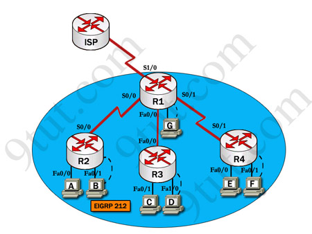
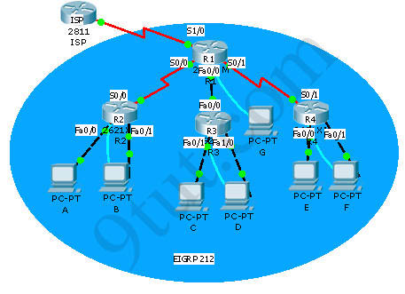
After adding R3 router, no routing updates are being exchanged between R3 and the new location. All other inter connectivity and Internet access for the existing locations of the company are working properly.
The task is to identify the fault(s) and correct the router configuration to provide full connectivity between the routers.
Access to the router CLI can be gained by clicking on the appropriate host. All passwords on all routers are cisco.
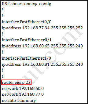
We should check the configuration of the new added router first because it does not function properly while others work well. From the command line interface of R3 router, enter the show running-config command
Image may be NSFW. Clik here to view.
From the output above, we know that this router was wrongly configured with an autonomous number (AS) of 22. When the AS numbers among routers are mismatched, no adjacency is formed.
(You should check the AS numbers on other routers for sure)
To solve this problem, we simply re-configure router R3 with the following commands:
R3>enable (you have to enter cisco as its password here)
R3#configure terminal
R3(config)#no router eigrp 22
R3(config)#router eigrp 212
R3(config-router)#network 192.168.60.0
R3(config-router)#network 192.168.77.0
R3(config-router)#no auto-summary
R3(config-router)#end
R3#copy running-config startup-config
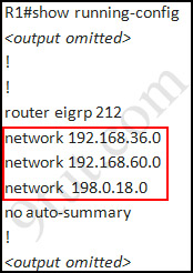
Check R1 router with the show running-config command:
Image may be NSFW. Clik here to view.
Notice that it is missing a definition to the network R3. Therefore we have to add it so that it can recognize R3 router
R1>enable (you have to enter cisco as its password here)
R1#configure terminal
R1(config)#router eigrp 212
R1(config-router)#network 192.168.77.0
R1(config-router)#end
R1#copy running-config startup-config
Now the whole network will work well. You should check again with ping command from router R3 to other routers!
Modifications:
Maybe in this EIGRP Sim you will see the “passive-interface …” command somewhere in R1 configuration. If the link between R1 to R2 (or R3, r4) routers has the “passive interface” then we have to remove it with the “no passive-interface …” command because it prevents EIGRP update from being sent on that interface. But if the “passive interface” is applied to the link between R1 and ISP router then we just leave it. Don’t use the “no passive-interface s1/0″ on R1 because the link between R1 & ISP doesn’t need EIGRP to run on it. A static route from R1 to ISP & “ip default-network” command in R1 are the correct answers.
(Note: The “ip default-network” command in R1 will advertise the static route of R1 (to go to the Internet) to other routers (R2,R3,R4) so that they can access the Internet too). In the exam you will see these lines in R1 configuration:
!
ip default-network 198.0.18.0
ip route 0.0.0.0 0.0.0.0 198.0.18.5
!
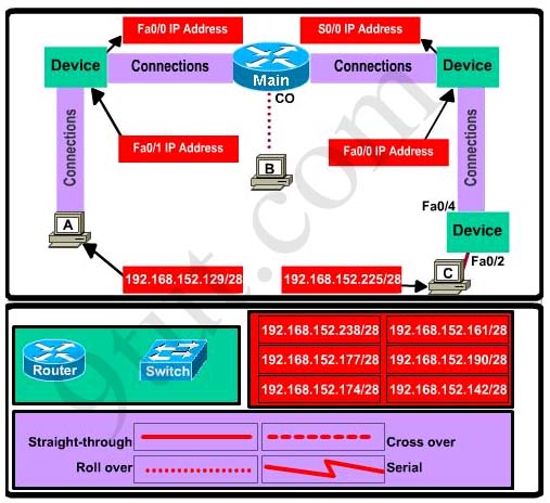
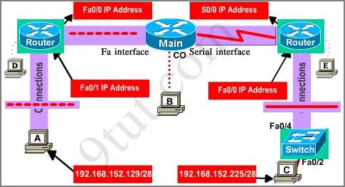
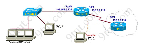
This topology contains 3 routers and 1 switch. Complete the topology.
Drag the appropriate device icons to the labeled Device
Drag the appropriate connections to the locations labeled Connections.
Drag the appropriate IP addresses to the locations labeled IP address
(Hint: use the given host addresses and Main router information)
To remove a device or connection, drag it away from the topology.
Use information gathered from the Main router to complete the configuration of any additional routers. No passwords are required to access the Main router. The config terminal command has been disabled for the HQ router. The router does not require any configuration.
Configure each additional router with the following:
Configure the interfaces with the correct IP address and enable the interfaces.
Set the password to allow console access to consolepw
Set the password to allow telnet access to telnetpw
Set the password to allow privilege mode access to privpw
Note: Because routes are not being added to the configurations, you will not be able to ping through the internetwork.
All devices have cable autosensing capabilities disabled.
All hosts are PC’s
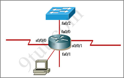
Specify appropriate devices and drag them on the “Device” boxes
For the device at the bottom-right box, we notice that it has 2 interfaces Fa0/2 and Fa0/4; moreover the link connects the PC on the right with the device on the bottom-right is a straight-through link -> it is a switch
The question stated that this topology contains 3 routers and 1 switch -> two other devices are routers
Place them on appropriate locations as following:
Image may be NSFW. Clik here to view.
(Host D and host E will be automatically added after placing two routers. Click on them to access neighboring routers)
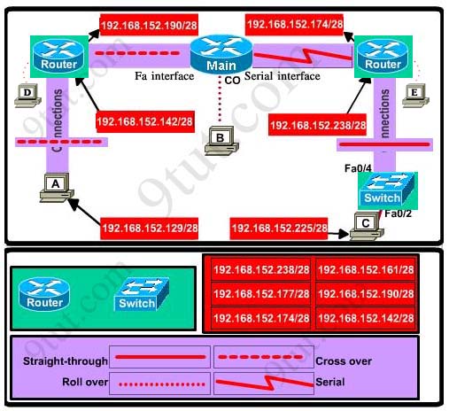
Specify appropriate connections between these devices:
+ The router on the left is connected with the Main router through FastEthernet interfaces: use a crossover cable
+ The router on the right is connected with the Main router through Serial interfaces: use a serial cable
+ The router on the right and the Switch: use a straight-through cable + The router on the left and the computer: use a crossover cable
(To remember which type of cable you should use, follow these tips:
- To connect two serial interfaces of 2 routers we use serial cable
– To specify when we use crossover cable or straight-through cable, we should remember: Group 1: Router, Host, Server Group 2: Hub, Switch
One device in group 1 + One device in group 2: use straight-through cable
Two devices in the same group: use crossover cable
For example: we use straight-through cable to connect switch to router, switch to host, hub to host, hub to server… and we use crossover cable to connect switch to switch, switch to hub, router to router, host to host… )
Image may be NSFW. Clik here to view.
Assign appropriate IP addresses for interfaces:
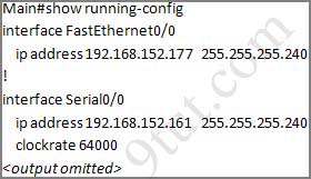
From Main router, use show running-config command:
Image may be NSFW. Clik here to view.
(Notice that you may see different IP addresses in the real CCNA exam, the ones shown above are just used for demonstration)
From the output we learned that the ip address of Fa0/0 interface of the Main router is 192.168.152.177/28. This address belongs to a subnetwork which has:
And we can pick up an ip address from the list that belongs to this subnetwork: 192.168.152.190 and assign it to the Fa0/0 interface the router on the left
Use the same method for interface Serial0/0 with an ip address of 192.168.152.161
You will need Packet Tracer version 5.3 or above to open these files. It’s totally free! You can download this software but you need to register first or you can find a mirror download with google (with keyword “download packet tracer”)
Please notice that in real exam, you have to click on host (PC) to access command-line-interface of the router, not the router itself.
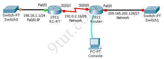
You work as a network technician at 9tut.com. Study the exhibit carefully. You are required to perform configurations to enable Internet access. The Router ISP has given you six public IP addresses in the 198.18.32.65 198.18.32.70/29 range.
9tut.com has 62 clients that needs to have simultaneous internet access. These local hosts use private IP addresses in the 192.168.6.65 – 192.168.6.126/26 range.
You need to configure Router1 using the PC1 console.
You have already made basic router configuration. You have also configured the appropriate NAT interfaces; NAT inside and NAT outside respectively.
Now you are required to finish the configuration of Router1.
The company has 62 hosts that need to access the internet simultaneously but we just have 6 public IP addresses from 198.18.32.65 to 198.18.32.70/29 => we have to use NAT overload (or PAT)
Double click on PC1 to access Router1′s command line interface
Router1>enable Router1#configure terminal
Create a NAT pool of global addresses to be allocated with their netmask (notice that /29 = 248)
Router1(config)#ip nat pool mypool 198.18.32.65 198.18.32.70 netmask 255.255.255.248
Create a standard access control list that permits the addresses that are to be translated
Establish dynamic source translation, specifying the access list that was defined in the prior step
Router1(config)#ip nat inside source list 1 pool mypool overload
This command translates all source addresses that pass access list 1, which means a source address from 192.168.6.65 to 192.168.6.126, into an address from the pool named mypool (the pool contains addresses from 198.18.32.65 to 198.18.32.70)
Overload keyword allows to map multiple IP addresses to a single registered IP address (many-to-one) by using different ports
The question said that appropriate interfaces have been configured for NAT inside and NAT outside statements.
This is how to configure the NAT inside and NAT outside, just for your understanding:
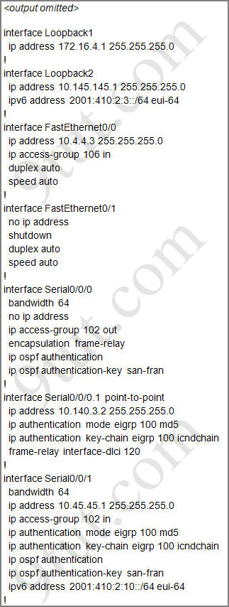
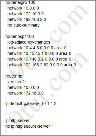
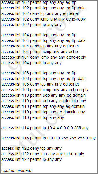
For this question we only need to use the show running-config command to answer all the questions below
Router>enable Router#show running-config
Image may be NSFW. Clik here to view.
Image may be NSFW. Clik here to view.
Image may be NSFW. Clik here to view.
Question 1:
Which will fix the issue and allow ONLY ping to work while keeping telnet disabled?
A – Correctly assign an IP address to interface fa0/1
B – Change the ip access-group command on fa0/0 from “in” to “out”
C – Remove access-group 106 in from interface fa0/0 and add access-group 115 in.
D – Remove access-group 102 out from interface s0/0/0 and add access-group 114 in
E – Remove access-group 106 in from interface fa0/0 and add access-group 104 in
Answer: E
Explanation:
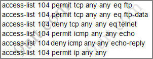
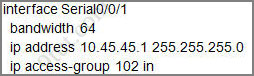
Let’s have a look at the access list 104:
Image may be NSFW. Clik here to view.
The question does not ask about ftp traffic so we don’t care about the two first lines. The 3rd line denies all telnet traffic and the 4th line allows icmp traffic to be sent (ping). Remember that the access list 104 is applied on the inbound direction so the 5th line “access-list 104 deny icmp any any echo-reply” will not affect our icmp traffic because the “echo-reply” message will be sent over the outbound direction.
Question 2:
What would be the effect of issuing the command ip access-group 114 in to the fa0/0 interface?
A – Attempts to telnet to the router would fail
B – It would allow all traffic from the 10.4.4.0 network
C – IP traffic would be passed through the interface but TCP and UDP traffic would not
D – Routing protocol updates for the 10.4.4.0 network would not be accepted from the fa0/0 interface
Answer: B
Explanation:
From the output of access-list 114: access-list 114 permit ip 10.4.4.0 0.0.0.255 any we can easily understand that this access list allows all traffic (ip) from 10.4.4.0/24 network
Question 3:
What would be the effect of issuing the command access-group 115 in on the s0/0/1 interface?
A – No host could connect to Router through s0/0/1
B – Telnet and ping would work but routing updates would fail.
C – FTP, FTP-DATA, echo, and www would work but telnet would fail
D – Only traffic from the 10.4.4.0 network would pass through the interface
Answer: A
Explanation:
First let’s see what was configured on interface S0/0/1:
Image may be NSFW. Clik here to view.
Recall that each interface only accepts one access-list, so when using the command “ip access-group 115 in” on the s0/0/1 interface it will overwrite the initial access-list 102. Therefore any telnet connection will be accepted (so we can eliminate answer C).
B is not correct because if telnet and ping can work then routing updates can, too.
D is not correct because access-list 115 does not mention about 10.4.4.0 network. So the most reasonable answer is A.
But here raise a question…
The wildcard mask of access-list 115, which is 255.255.255.0, means that only host with ip addresses in the form of x.x.x.0 will be accepted. But we all know that x.x.x.0 is likely to be a network address so the answer A: “no host could connect to Router through s0/0/1” seems right…
But what will happen if we don’t use a subnet mask of 255.255.255.0? For example we can use an ip address of 10.45.45.0 255.255.0.0, such a host with that ip address exists and we can connect to the router through that host. Now answer A seems incorrect!
This topic describes the features that VLAN Trunking Protocol (VTP) offers to support VLANs. To help you understand the basic concept, this is a summary of what VTP is:
“VTP allows a network manager to configure a switch so that it will propagate VLAN configurations to other switches in the network”
VTP minimizes misconfigurations and configuration inconsistencies that can cause problems, such as duplicate VLAN names or incorrect VLAN-type specifications. VTP helps you simplify management of the VLAN database across multiple switches.
VTP is a Cisco-proprietary protocol and is available on most of the Cisco switches.
Why we need VTP?
To answer this question, let’s discuss a real and popular network topology.
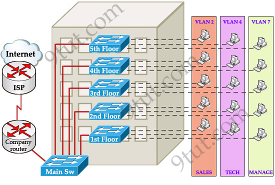
Suppose you are working in a medium company in a 5-floor office. You assigned each floor to a switch for easy management and of course they can be assigned to different VLANs. For example, your bosses can sit in any floor and still access Manage VLAN (VLAN 7). Your technical colleagues can sit anywhere on the floors to access Technical VLAN (VLAN 4). This is the best design because each person’s permission is not limited by the physical location.
Image may be NSFW. Clik here to view.
Now let’s discuss about VTP role in this topology! Suppose VTP is not running on these switches. One day, your boss decides to add a new department to your office, the Support Department, and you are tasked to add a new SUPPORT VLAN for this department. How will you do that? Well, without VTP you have to go to each switch to enable this new VLAN. Fortunately your office only has 5 floors so you can finish this task in some hours :)
But just imagine if your company was bigger with 100-floor office and some VLANs needed to be added every month! Well, it will surely become a daunting task to add a new VLAN like this. Luckily, Cisco always “thinks big” to create a method for you to just sit at the “Main Sw”, adding your new VLANs and magically, other switches automatically learn about this VLAN, sweet, right? It is not a dream, it is what VTP does for you!
How VTP Works
To make switches exchange their VLAN information with each other, they need to be configured in the same VTP domain. Only switches belonging to the same domain share their VLAN information. When a change is made to the VLAN database, it is propagated to all switches via VTP advertisements.
To maintain domain consistency, only one switch should be allowed to create (or delete, modify) new VLAN. This switch is like the “master” of the whole VTP domain and it is operated in Server mode. This is also the default mode.
Other switches are only allowed to receive and forward updates from the “server” switch. They are operated in Client mode.
Image may be NSFW. Clik here to view.
In some cases, the network manager doesn’t want a switch to learn VTP information from other switches. He can set it to Transparent mode. In this mode, a switch maintains its own VLAN database and never learn VTP information from other switches (even the server). However, it still forwards VTP advertisements from the server to other switches (but doesn’t read that update). A transparent switch can add, delete and modify VLAN database locally.
Now return to the example above, we can configure any switches as the “server” but for our convenience, the “Main Sw” should be assigned this function and we should place it in a safe place.
Image may be NSFW. Clik here to view.
As said above, VTP advertisements bring VLAN information to all the switches in a VTP domain. Each VTP advertisement is sent with a Revision number. This number is used in order to determine whether the VTP advertisement is more recent than the current version of that switch. Because each time you make a VLAN change in a switch, the configuration revision is incremented by one. So the higher the revision number, the better your VTP advertisement.
For example, the first time the Main Sw sends a VTP advertisement, its Revision number is 1. When you add a new VLAN to the Main Sw, it will send a VTP advertisement with the Revision number of 2. Client switches first receive the VTP advertisement with the Revision number of 1, which is bigger than its current Revision number (0) so it updates its VLAN database. Next it receives the VTP advertisement with the Revision number of 2, it continues comparing with its current Revision number (1) -> it continues update its VLAN database.
One important thing you must know is when a switch receives a better VTP advertisement, it deletes its whole VTP information and copy the new information from the better VTP advertisement to its VLAN database. A switch does not try to compare its own VLAN database with information from the received VTP advertisements to find out and update the difference!
Note: VTP advertisements are sent as multicast frames and all neighbors in that domain receive the frames.
The “show vtp status” command analysis
The most important command to view the status of VTP on Cisco switches that each CCNA learners must grasp is the “show vtp status” command. Let’s have a look at the output of this command:
Image may be NSFW. Clik here to view.
+ VTP Version: displays the VTP version the switch is running. By default, the switch runs version 1 but can be set to version 2. Within a domain, the two VTP versions are not interoperable so make sure to configure the same VTP version on every switch in a domain.
+ Configuration Revision: current Revision number on this switch.
+ Maximum VLANs Supported Locally: maximum number of VLANs supported locally.
+ Number of Existing VLANs: Number of existing VLANs.
+ VTP Operating Mode: can be server, client, or transparent.
+ VTP Domain Name: name that identifies the administrative domain for the switch.
By default, a switch operates in VTP Server mode with a NULL (blank) domain name with no password configured (the password field is not listed in the output)
+ VTP Pruning Mode: displays whether pruning is enabled or disabled. We will discuss about VTP Pruning later.
+ VTP V2 Mode: displays if VTP version 2 mode is enabled. VTP version 2 is disabled by default.
+ VTP Traps Generation: displays whether VTP traps are sent to a network management station.
+ MD5 Digest: a 16-byte checksum of the VTP configuration.
+ Configuration Last Modified: date and time of the last configuration modification. Displays the IP address of the switch that caused the configuration change to the database.
VTP Pruning
To understand what VTP Pruning is, let’s see an example:
Image may be NSFW. Clik here to view.
When PC A sends a broadcast frame on VLAN 10, it travels across all trunk links in the VTP domain. Switches Server, Sw2, and Sw3 all receive broadcast frames from PC A. But only Sw3 has user on VLAN 10 and it is a waste of bandwidth on Sw2. Moreover, that broadcast traffic also consumes processor time on Sw2. The link between switches Server and Sw2 does not carry any VLAN 10 traffic so it can be “pruned”.
Image may be NSFW. Clik here to view.
VTP Pruning makes more efficient use of trunk bandwidth by forwarding broadcast and unknown unicast frames on a VLAN only if the switch on the receiving end of the trunk has ports in that VLAN. In the above example, Server switch doesn’t send broadcast frame to Sw2 because Sw2 doesn’t have ports in VLAN 10.
When a switch has a port associated with a VLAN, the switch sends an advertisement to its neighbors to inform that it has active ports on that VLAN. For example, Sw3 sends an advertisement to Server switch to inform that it has active port for VLAN 10. Sw2 has not advertised about VLAN 10 so Server switch will prune VLAN 10 on the trunk to Sw2.
You only need to enable pruning on one VTP server switch in the domain.
VTP Configuration
Main Sw(config)#vtp version 2
Main Sw(config)#vtp domain 9tut
Main Sw(config)#vtp mode server
Main Sw(config)#vtp password keepitsecret
Notice: Before configuring VTP make sure the links between your switches are trunk links. Your trunk link can automatically be formed if both of your switches are not 2960 or 3560 because ports on the 2960 and 3560 switches are set to dynamic auto by default. If both sides are set to dynamic auto, the link will remain in access mode. To configure trunk between these ports, use these commands:
Client(config)#interface fa0/1 (or the interface on the link you want to be trunk) Client(config-if)#switchport mode trunk
These commands only need to be used on one of two switches to form the trunk.
Below summaries important notes about VTP:
+ Whenever a change occurs in the VLAN database, the VTP server increments its configuration revision number and then advertises the new revision throughout the VTP domain via VTP advertisements.
+ VTP operates in one of three modes: server, transparent, or client.
VTP modes:
* Server: The default mode. When you make a change to the VLAN configuration on a VTP server, the change is propagated to all switches in the VTP domain. VTP messages are transmitted out of all the trunk connections. In Server mode we can create, modify, delete VLANs.
* Client: cannot make changes to the VLAN configuration when in this mode; however, a VTP client can send any VLANs currently listed in its database to other VTP switches. VTP client also forwards VTP advertisements (but cannot create VTP advertisements).
* Transparent: When you make a change to the VLAN configuration in this mode, the change affects only the local switch and does not propagate to other switches in the VTP domain. VTP transparent mode does forward VTP advertisements that it receives within the domain.
VTP Pruning makes more efficient use of trunk bandwidth by forwarding broadcast and unknown unicast frames on a VLAN only if the switch on the receiving end of the trunk has ports in that VLAN.
For more information about VTP, I highly recommend you to visit the official tutorial about VTP published by Cisco. It is very comprehensive: http://www.cisco.com/warp/public/473/vtp_flash/
“A virtual LAN (VLAN) is a group of networking devices in the same broadcast domain”
It is the concept of VLAN that most of the books are using but it doesn’t help us understand the benefits of VLANs. If you ask “What is a LAN?” you will receive the same answer: it is also a group of networking devices in the same broadcast domain!
To make it clearer, I expanded the above statement into a bit longer statement :)
“A virtual LAN (VLAN) is a group of networking devices in the same broadcast domain, logically”
It means that the devices in the same VLAN may be widely separated in the network, both by geography and location. VLANs logically segment the network into different broadcast domains so that packets are only switched between ports that are designated for the same VLAN.
Let’s take an example to understand the benefits of VLAN. Suppose you are working in a big company with many departments, some of them are SALES and TECHNICAL departments. You are tasked to separate these departments so that each of them can only access specific resources in the company.
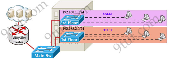
This task is really easy, you think. To complete this task, you just need to use different networks for these departments and use access-list to allow/deny that network to a specific resource. For example, you assign network 192.168.1.0/24 for SALES and 192.168.2.0/24 for TECH. At the “Company router” you apply an access-list to filter traffic from these networks. Below is the topology of your network without VLANs:
Image may be NSFW. Clik here to view.
Everything looks good and you implement this design to your company. But after one month you receive many complaints from both your colleagues and leaders.
+ First, your department leaders need to access to additional private resources which employees are not allowed.
+ Second, the company has just recruited some new SALES employees but now the SALES room is full so they have to sit at the 1st floor (in the TECH area). They want to access to SALES resources but they can only access to the TECH resources because they are connecting to TECH switch.
To solve the first problem maybe you will create a new and more powerful network for your leaders. But notice that each leader sits at different floor so you will need to link all of them to a switch -> what a mess!
The second problem is more difficult than the first one. Maybe you have to create another network at the TECH area and apply the same policy as the SALES department for these hosts -> another mess in management!
Maybe you will be glad to know VLAN can solve all these problems. VLAN helps you group users together according to their function rather than their physical location. This means you can use the same network for hosts in different floors (of course they can communicate with each other).
Image may be NSFW. Clik here to view.
In this design:
+ you can logically create a new network with additional permissions for your leaders (LEADER network) by adding another VLAN.
+ employees can sit anywhere to access the resources in their departments, provided that you allow them to do so.
+ computers in the same department can communicate with each other although they are at different floors.
If these departments expand in the future you can still use the same network in any other floor. For example, SALES needs to have 40 more employees -> you can use 4th floor for this expansion without changing the current network.
But wait… maybe you recognize something strange in the above design? How can 2 computers connecting to 2 different switches communicate? If one computer sends a broadcast packet will it be flooded to other departments as switch doesn’t break up broadcast domains?
The answer is “Yes, they can!” and it is the beauty of VLAN. Hosts in the same VLAN can communicate normally even they are connecting to 2 or more different switches. This makes the management much more simple.
Although layer 2 switches can only break up collision domains but VLANs can be used to break up broadcast domains. So if a computer in SALES broadcasts, only computers in SALES will receive that frame.
So we don’t need a router, right? The answer is “we still need a router” to enable different VLANs to communicate with each other. Without a router, the computers within each VLAN can communicate with each other but not with any other computers in another VLAN. For example, we need a router to transfer file from LEADER to TECH. This is called “interVLAN routing”.
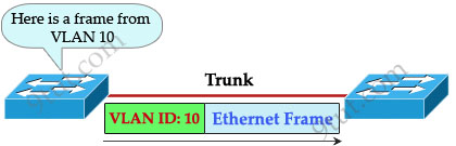
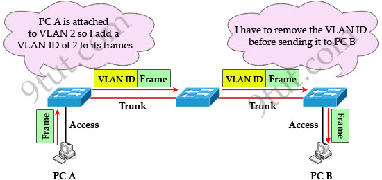
When using VLANs in networks that have multiple interconnected switches, you need to use VLAN trunking between the switches. With VLAN trunking, the switches tag each frame sent between switches so that the receiving switch knows which VLAN the frame belongs to. This tag is known as a VLAN ID. A VLAN ID is a number which is used to identify a VLAN.
Image may be NSFW. Clik here to view.
Notice that the tag is only added and removed by the switches when frames are sent out on the trunk links. Hosts don’t know about this tag because it is added on the first switch and removed on the last switch. The picture below describes the process of a frame sent from PC A to PC B.
Image may be NSFW. Clik here to view.
Note: Trunk link does not belong to a specific VLAN, rather it is a conduit for VLANs between switches and routers.
To allow interVLAN routing you need to configure trunking on the link between router and switch.
Therefore in our example we need to configure 3 links as “trunk”.
Image may be NSFW. Clik here to view.
Cisco switches support two different trunking protocols, Inter-Switch Link (ISL) and IEEE 802.1q. Cisco created ISL before the IEEE standardized trunking protocol. Because ISL is Cisco proprietary, it can be used only between two Cisco switches -> 802.1q is usually used in practical.
In 802.1q encapsulation, there is a concept called native VLAN that was created for backward compatibility with old devices that don’t support VLANs. Native VLAN works as follows:
+ Frame belonging to the native VLAN is not tagged when sent out on the trunk links
+ Frame received untagged on the trunk link is set to the native VLAN.
Image may be NSFW. Clik here to view.
So if an old switch doesn’t support VLAN it can still “understand” that frame and continue sending it (without dropping it).
Every port belongs to at least one VLAN. If a switch receives untagged frames on a trunkport, they are assumed to be part of the native vlan. By default, VLAN 1 is the default and native VLAN but this can be changed on a per port basis by configuration.
In this article we will create a Frame Relay in GNS3 to learn how to configure Frame-Relay.
Note: If you need to revise your Frame Relay knowledge, we recommend you to read our Frame Relay tutorial first.
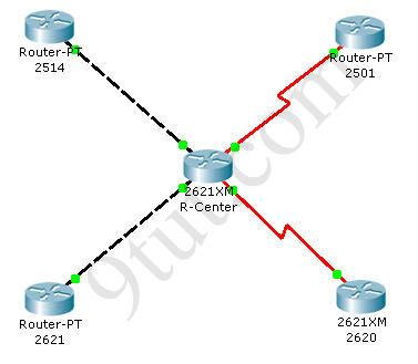
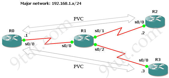
First we create 4 routers and link them as follows:
Image may be NSFW. Clik here to view.
IOS used in this lab: c2600-bin-mz.123-6f.bin
Configure IP addresses
First we will assign IP addresses for all relevant interfaces. Notice that R1 will be Frame-Relay switch in this lab so its interfaces don’t need IP addresses.
To configure Frame-Relay on R0, R2 and R3 we need to enable Frame-Relay encapsulation and specify a type of LMI (ansi – in this case). Notice that Inverse ARP is enabled by default on Cisco routers so we don’t need to type anything to activate it.
In this lab R1 will be configured as a Frame-relay switch so no IP address is required.
Turn on Frame-Relay switching feature on R1: R1(config)#frame-relay switching
On each interface we must specify how the frame will be proceeded. In practical, the Frame-Relay switch (R1) is placed at the ISP side so its interfaces should be set to DCE.
R1(config)# interface s0/0
R1(config-if)#encapsulation frame-relay
R1(config-if)#frame-relay lmi-type ansi
R1(config-if)#frame-relay intf-type dce //This command specifies the interface to handle LMI like a Frame Relay DCE device.
R1(config-if)#clock rate 64000
R1(config-if)#frame-relay route 102 interface Serial0/1 201 (will be explained later)
R1(config-if)#frame-relay route 103 interface Serial0/2 301
The command frame-relay route 102 interface Serial0/1 201 means frame-relay traffic come to R1 which has a DLCI of 102 will be sent to interface Serial0/1 with a DLCI of 201.
Note: Data link connection identifiers (DLCIs) are numbers that refer to paths through the Frame Relay network. They are only locally significant.
Continue configuring s0/1 & s0/2 interfaces (same as s0/0)
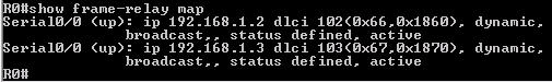
Use the show frame-relay map command to display the current map entries for static and dynamic routes
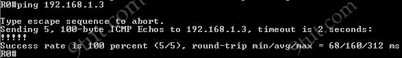
R0#show frame-relay map
Image may be NSFW. Clik here to view.
By default, Cisco uses Inverse ARP to map remote IP address of the PVC with the DLCI of the local interface as we can see here. From the output above we learn that DLCI 102 is set on Serial0/0 of R0 and mapped with 192.168.1.2. The status of this connection is “dynamic” and “active”, which means it is operating correctly.
The outputs of this command on other routers are shown below:
Image may be NSFW. Clik here to view.
Image may be NSFW. Clik here to view.
Notice that you will only see the “map” at two ends. If we issue this command on Frame-Relay switch (R1 is this case) it will show nothing.
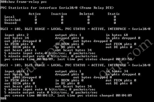
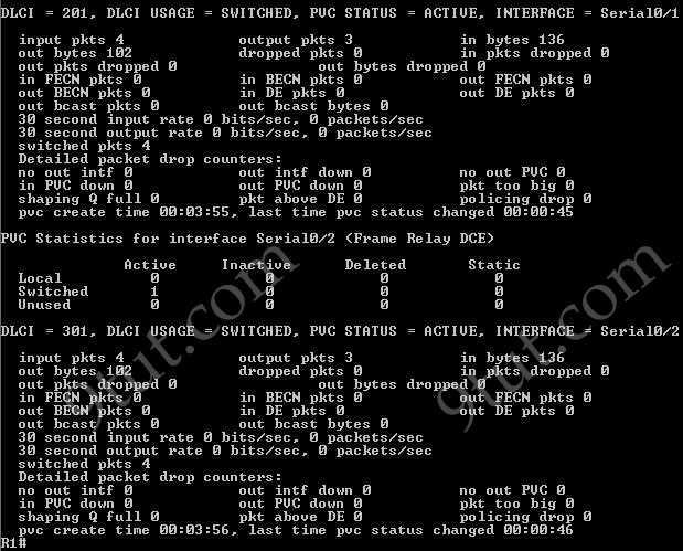
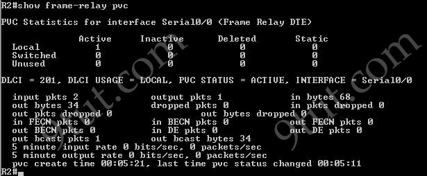
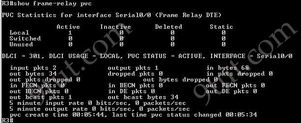
The show frame-relay pvc command is used to display the status of all configured connections, traffic statistics, BECN and FECN packets received by the router.
Image may be NSFW. Clik here to view.
Image may be NSFW. Clik here to view.
Image may be NSFW. Clik here to view.
Image may be NSFW. Clik here to view.
Image may be NSFW. Clik here to view.
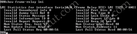
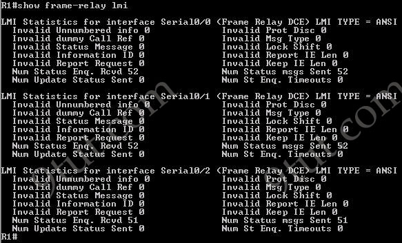
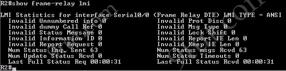
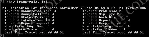
Use the show frame-relay lmi to display LMI traffic statistics (including LMI type, status messages sent and invalid LMI messages)
Image may be NSFW. Clik here to view.
Image may be NSFW. Clik here to view.
Image may be NSFW. Clik here to view.
Image may be NSFW. Clik here to view.
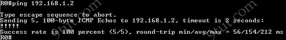
Pings from R0 to R2 & R3 are successful.
Image may be NSFW. Clik here to view.
Image may be NSFW. Clik here to view.
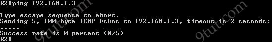
However ping from R2 to R3 is unsuccessful. It means that customers cannot see each other. This is because the split horizon rule: “A router never sends information about a route back in same direction which is original information came”. To overcome this problem we can configure subinterfaces on R0.
In this article we will discuss about Wireless technologies mentioned in CCNA.
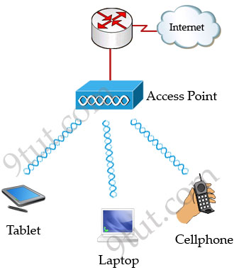
Wireless LAN (WLAN) is very popular nowadays. Maybe you have ever used some wireless applications on your laptop or cellphone. Wireless LANs enable users to communicate without the need of cable. Below is an example of a simple WLAN:
Image may be NSFW. Clik here to view.
Each WLAN network needs a wireless Access Point (AP) to transmit and receive data from users. Unlike a wired network which operates at full-duplex (send and receive at the same time), a wireless network operates at half-duplex so sometimes an AP is referred as a Wireless Hub.
The major difference between wired LAN and WLAN is WLAN transmits data by radiating energy waves, called radio waves, instead of transmitting electrical signals over a cable.
Also, WLAN uses CSMA/CA (Carrier Sense Multiple Access with Collision Avoidance) instead of CSMA/CD for media access. WLAN can’t use CSMA/CD as a sending device can’t transmit and receive data at the same time. CSMA/CA operates as follows:
+ Listen to ensure the media is free. If it is free, set a random time before sending data
+ When the random time has passed, listen again. If the media is free, send the data. If not, set another random time again
+ Wait for an acknowledgment that data has been sent successfully
+ If no acknowledgment is received, resend the data
IEEE 802.11 standards:
Nowadays there are three organizations influencing WLAN standards. They are:
+ ITU-R: is responsible for allocation of the RF bands
+ IEEE: specifies how RF is modulated to transfer data
+ Wi-Fi Alliance: improves the interoperability of wireless products among vendors
But the most popular type of wireless LAN today is based on the IEEE 802.11 standard, which is known informally as Wi-Fi.
* 802.11a: operates in the 5.7 GHz ISM band. Maximum transmission speed is 54Mbps and approximate wireless range is 25-75 feet indoors. * 802.11b: operates in the 2.4 GHz ISM band. Maximum transmission speed is 11Mbps and approximate wireless range is 100-200 feet indoors. * 802/11g: operates in the 2.4 GHz ISM band. Maximum transmission speed is 54Mbps and approximate wireless range is 100-200 feet indoors.
ISM Band: The ISM (Industrial, Scientific and Medical) band, which is controlled by the FCC in the US, generally requires licensing for various spectrum use. To accommodate wireless LAN’s, the FCC has set aside bandwidth for unlicensed use including the 2.4Ghz spectrum where many WLAN products operate.
Wi-Fi: stands for Wireless Fidelity and is used to define any of the IEEE 802.11 wireless standards. The term Wi-Fi was created by the Wireless Ethernet Compatibility Alliance (WECA). Products certified as Wi-Fi compliant are interoperable with each other even if they are made by different manufacturers.
Access points can support several or all of the three most popular IEEE WLAN standards including 802.11a, 802.11b and 802.11g.
WLAN Modes:
WLAN has two basic modes of operation:
* Ad-hoc mode: In this mode devices send data directly to each other without an AP.
Image may be NSFW. Clik here to view.
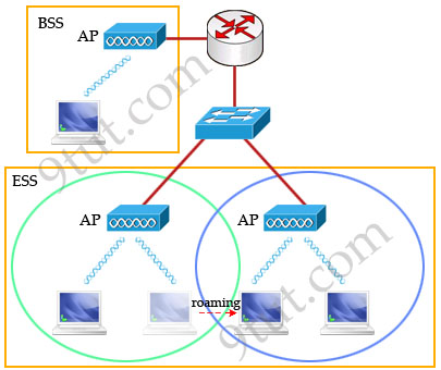
* Infrastructure mode: Connect to a wired LAN, supports two modes (service sets):
+ Basic Service Set (BSS): uses only a single AP to create a WLAN
+ Extended Service Set (ESS): uses more than one AP to create a WLAN, allows roaming in a larger area than a single AP. Usually there is an overlapped area between two APs to support roaming. The overlapped area should be more than 10% (from 10% to 15%) to allow users moving between two APs without losing their connections (called roaming). The two adjacent APs should use non-overlapping channels to avoid interference. The most popular non-overlapping channels are channels 1, 6 and 11 (will be explained later).
Image may be NSFW. Clik here to view.
Roaming: The ability to use a wireless device and be able to move from one access point’s range to another without losing the connection.
When configuring ESS, each of the APs should be configured with the same Service Set Identifier (SSID) to support roaming function. SSID is the unique name shared among all devices on the same wireless network. In public places, SSID is set on the AP and broadcasts to all the wireless devices in range. SSIDs are case sensitive text strings and have a maximum length of 32 characters. SSID is also the minimum requirement for a WLAN to operate. In most Linksys APs (a product of Cisco), the default SSID is “linksys”.
In the next part we will discuss about Wireless Encoding, popular Wireless Security Standard and some sources of wireless interference.
Let’s start this article with the question: Why do we need Frame Relay?
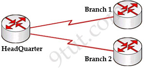
Let’s take a simple example. Suppose you are working in a big company and your company has just expanded to two new locations. The main site is connected to two branch offices, named Branch 1 & Branch 2 and your boss wants these two branches can communicate with the main site. The most simple solution is to connect them directly (called a leased line) as shown below:
Image may be NSFW. Clik here to view.
To connect to these two branches, the main site router, HeadQuarter, requires two serial interfaces which a router can provide. But what happens when the company expands to 10 branches, 50 branches? For each point-to-point line, HeadQuarter needs a separate physical serial interface (and maybe a separate CSU/DSU if it is not integrated into the WAN card). As you can imagine, it will need many routers with many interfaces and lots of rack space for the routers and CSU/DSUs. Maybe we should use another solution for this problem? Luckily, Frame Relay can do it!
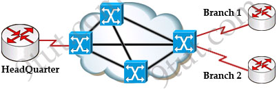
By using Frame Relay we only need one serial interface at the HeadQuarter to connect to all branches. This is also true when we expand to 10 or 50 branches. Moreover, the cost is much lesser than using leased-lines.
Image may be NSFW. Clik here to view.
Frame Relay is a high-performance WAN protocol that operates at the physical and data link layers of the OSI reference model. It offers lower-cost data transfer when compared to typical point-to-point applications, by using virtual connections within the frame relay network and by combining those connections into a single physical connection at each location. Frame relay providers use a frame relay switch to route the data on each virtual circuit to the appropriate destination.
Maybe these terminologies of Frame Relay are difficult to understand so we will explain them in more detail in this article.
DCE & DTE
The first concept in Frame Relay you must grasp is about DTE & DCE:
+ Data terminal equipment (DTE), which is actually the user device and the logical Frame-relay end-system
+ Data communication equipment (DCE, also called data circuit-terminating equipment), which consists of modem and packet switch
In general, the routers are considered DTE, and the Frame Relay switches are DCE. The purpose of DCE equipment is to provide clocking and switching services in a network. In our example, HeadQuarter, Branch 1 & Branch 2 are DTEs while Frame Relay switches are DCEs.
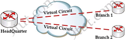
Virtual Circuits
The logical connection through the Frame Relay network between two DTEs is called a virtual circuit (VC). The term “virtual” here means that the two DTEs are not connected directly but through a network. For example, the HeadQuarter & Branch 1 (or Branch 2) can communicate with each other as if they were directly connected but in fact they are connected through a Frame Relay network with many Frame Relay switches between them.
Image may be NSFW. Clik here to view.
There are two types of VCs
+ switched virtual circuits (SVCs): are temporary connections that are only used when there is sporadic data transfer between DTE devices across the Frame Relay network. SVC is set up dynamically when needed. SVC connections require call setup and termination for each connection.
+ permanent virtual circuits (PVCs): A predefined VC. A PVC can be equated to a leased line in concept.
Nowadays most service providers offer PVC service only to save additional costs for signaling and billing procedures.
In this article, we will learn how to subnet and make subnetting an easy task.
The table below summarizes the possible network numbers, the total number of each type, and the number of hosts in each Class A, B, and C network.
Default subnet mask
Range
Class A
255.0.0.0 (/8)
1.0.0.0 – 126.255.255.255
Class B
255.255.0.0 (/16)
128.0.0.0 – 191.255.255.255
Class C
255.255.255.0 (/24)
192.0.0.0 – 223.255.255.255
Table 1 – Default subnet mask & range of each class
Class A addresses begin with a 0 bit. Therefore, all addresses from 1.0.0.0 to 126.255.255.255 belong to class A (1=0000 0001; 126 = 0111 1110).
The 0.0.0.0 address is reserved for default routing and the 127.0.0.0 address is reserved for loopback testing so they don’t belong to any class.
Class B addresses begin with a 1 bit and a 0 bit. Therefore, all addresses from 128.0.0.0 to 191.255.255.255 belong to class B (128=1000 0000; 191 = 1011 1111).
Class C addresses begin with two 1 bits and a 0 bit. Class C addresses range from 192.0.0.0 to 223.255.255.255 (192 = 1100 0000; 223 = 1101 1111).
Class D & E are used for Multicast and Research purposes and we are not allowed to subnet them so they are not mentioned here.
Note: The number behind the slash notation (/) specifies how many bits are turned on (bit 1). For example:
+ “/8″ equals “1111 1111.0000 0000.0000 0000.0000 0000″ -> 8 bits are turned on (bit 1)
+ “/12″ equals “1111 1111.1111 0000.0000 0000.0000 0000″ -> 12 bits are turned on (bit 1)
+ “/28″ equals “1111 1111.1111 1111.1111 1111.1111 0000″ -> 28 bits are turned on (bit 1)
+ “/32″ equals “1111 1111.1111 1111.1111 1111.1111 1111″ -> 32 bits are turned on (bit 1) and this is also the maximum value because all bits are turned on.
The slash notation (following with a number) is equivalent to a subnet mask. If you know the slash notation you can figure out the subnet mask and vice versa. For example, “/8″ is equivalent to “255.0.0.0″; “/12″ is equivalent to “255.240.0.0″; “/28″ is equivalent to “255.255.255.240″; “/32″ is equivalent to “255.255.255.255″.
Image may be NSFW. Clik here to view.
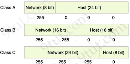
The Network & Host parts of each class by default
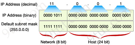
From the “default subnet mask” shown above, we can identify the network and host part of each class. Notice that in the subnet mask, bit 1 represents for Network part while bit 0 presents for Host part (255 equals to 1111 1111 and 0 equals to 0000 0000 in binary form).
What is “subnetting”?
When changing a number in the Network part of an IP address we will be in a different network from the previous address. For example, the IP address 11.0.0.1 belongs to class A and has a default subnet mask of 255.0.0.0; if we change the number in the first octet (a block of 8 bits, the first octet is the leftmost 8 bits) we will create a different network. For example, 12.0.0.1 is in a different network from 11.0.0.1. But if we change a number in the Host part, we are still in the same Network. For example, 11.1.0.1 is in the same network of 11.0.0.1.
The problem here is if we want to create 300 networks how can we do that? In the above example, we can only create different networks when changing the first octet so we can create a maximum of 255 networks because the first octet can only range from 1 to 255 (in fact it is much smaller because class A only range from 1 to 126). Now we have to use a technique called “subnetting” to achieve our purpose.
“Subnetting” means we borrow some bits from the Host part to add to the Network part. This allows us to have more networks than using the default subnet mask. For example, we can borrow some bits in the next octet to make the address 11.1.0.1 belong to a different network from 11.0.0.1.
How to subnet?
Do you remember that I said “in the subnet mask, bit 1 represents for Network part while bit 0 presents for Host part”? Well, this also means that we can specify how many bits we want to borrow by changing how many bit 0 to bit 1 in the subnet mask.
Let’s come back to our example with the IP 11.0.0.1, we will write all numbers in binary form to reveal what a computer really sees in an IP address.
Image may be NSFW. Clik here to view.
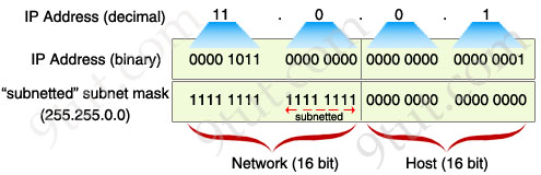
Now you can clearly see that the subnet mask will decide which is the Network part, which is the Host part. By borrowing 8 bits, our subnet mask will be like this:
Image may be NSFW. Clik here to view.
After changing the second octet of the subnet mask from all “0″ to all “1″, the Network part is now extended. Now we can create new networks by changing number in the first or second octet. This greatly increases the number of networks we can create. With this new subnet mask, IP 11.1.0.1 is in different network from IP 11.0.0.1 because “1″ in the second octet now belongs to the Network part.
So, in conclusion we “subnet” by borrowing bit “0″ in the Host portion and converting them to bit “1″. The number of borrowed bits is depended on how many networks we need.
Note: A rule of borrowing bits is we can only borrow bit 0 from the left to the right without skipping any bit 0. For example, you can borrow like this: “1111 1111. 1100 0000.0000 0000.0000 0000″ but not this: “1111 1111. 1010 0000.0000 0000.0000 0000″. In general, just make sure all your bit “1″s are successive on the left and all your bit “0″s are successive on the right.
In the next part we will learn how to calculate the number of sub-networks and hosts-per-subnet
Here you will find answers to CCNA – Protocols & Services Questions
Question 1
An administrator attempts a traceroute but receives a “Destination Unreachable” message. Which protocol is responsible for that message?
A. RARP
B. RUDP
C. ICMP
D. SNMP
Answer: C
Explanation
The ICMP destination unreachable message is generated by a router (which is reachable) to inform the source host that the destination unicast address is unreachable.
Question 2
DNS servers provide what service?
A. They run a spell check on host names to ensure accurate routing
B. They convert domain names into IP address
C. Given an IP address.they determine the name of the host that is sought
D. They map individual hosts to their specific IP addresses
Answer: B
Explanation
For example, when you open a web browser (IE, Firefox…) and type a domain (like google.com). This domain will be sent to a DNS server. The DNS server looks up this domain in its database and sends back a corresponding IP address which you can use to access that website.
Note: A DNS server can be a dedicated device for DNS service or integrated into a networking device (like router).
Question 3
Which of the following protocols uses both TCP and UDP ports?
A. SMTP
B. Telnet
C. FTP
D. DNS
Answer: D
Explanation
DNS can use either the User Datagram Protocol (UDP) or Transmission Control Protocol (TCP) with a destination port of 53.
Note:
+Simple Mail Transfer Protocol (SMTP) is specified for mail transport and uses TCP port 25.
+ Telnet uses TCP on port 23.
+ File Transfer Protocol (FTP) uses TCP on port 20, 21.
+ Trivial File Transfer Protocol (TFTP) uses UDP on port 69.
+ HTTP Secure (HTTPS) uses TCP on port 443.
Question 4
Which protocol should be used to establish a secure terminal connection to a remote network device?
A. ARP
B. SSH
C. Telnet
D. WEP
E. SNMPv1
F. SNMPv2
Answer: B
Explanation
Secure Shell (SSH) protocols secure terminal session data across insecure environments such as the internet.
Question 5
A network administrator issues the ping 192.168.2.5 command and successfully tests connectivity to a host that has been newly connected to the network. Which protocols were used during the test? (Choose two)
A. ARP
B. CDP
C. DHCP
D. DNS
E. ICMP
Answer: A E
Explanation
In this question we are not sure the host 192.168.2.5 is in or outside the local network. But in both cases the ARP protocol are used to get the MAC address:
+ If host 192.168.2.5 is inside the local network, our device will broadcast an ARP Request to ask the MAC address of the host 192.168.2.5 (something like “If your IP is 192.168.2.5, please send me your MAC address”).
+ If host 192.168.2.5 is outside the local network, our device will broadcast an ARP Request to ask the MAC address of the local port (the port in the same subnet with our device) of the default gateway. Notice that the IP of the default gateway has been already configured in our device.
-> In both cases, our device must broadcast an ARP Request -> A is correct.
After getting the ARP of the destination device, our device will use ICMP protocol to send the “ping” -> E is correct.
Note: The question states “the host has been newly connected to the network” which means our device hasn’t had the MAC address of this host in its ARP table -> it needs to send ARP Request.
There is one situation which makes answer A incorrect: the newly connected host is outside the network but our device has already learned the MAC address of the default gateway -> in this case no ARP Request will be sent. So I assume the question wants to imply the newly connected host is in the local network.
Question 6
Which network protocol does DNS use?
A. FTP
B. TFTP
C. TCP
D. UDP
E. SCP
Answer: D
Explanation
It is funny that in Question 3 I answered “DNS uses both TCP & UDP” but in this question we can only choose one answer and it should be “DNS uses UDP”. So I wish to explain more:
Normally a client sends a DNS Query using UDP Protocol over Port 53. If it does not get response from a DNS Server, it must re-transmit the DNS Query using TCP after 3-5 seconds. So we can say DNS prefers using UDP to TCP -> the answer should be UDP.
Question 7
When two hosts are trying to communicate across a network, how does the host originating the communication determine the hardware address of the host that it wants to “talk” to?
A. RARP request
B. Show Network Address request
C. Proxy ARP request
D. ARP request
E. Show Hardware Address request
Answer: D
Explanation
The address resolution protocol (ARP) is a protocol used to map IP network addresses to the hardware addresses.
+ If the destination host is inside the local network, the originating host will broadcast an ARP Request to ask the MAC address of that host.
+ If the destination host is outside the local network, the originating host will broadcast an ARP Request to ask the MAC address of the local port (the port in the same subnet with our device) of the default gateway. Notice that the IP of the default gateway has been already configured in our device.
Question 8
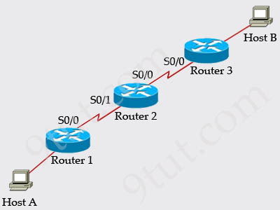
Refer to the exhibit, Host A pings interface S0/0 on router 3, what is the TTL value for that ping?
Image may be NSFW. Clik here to view.
A. 253
B. 252
C. 255
D. 254
Answer: A
Explanation
From the CCNA ICND2 Exam book: “Routers decrement the TTL by 1 every time they forward a packet; if a router decrements the TTL to 0, it throws away the packet. This prevents packets from rotating forever.” I want to make it clear that before the router forwards a packet, the TTL is still remain the same. For example in the topology above, pings to S0/1 and S0/0 of Router 2 have the same TTL.
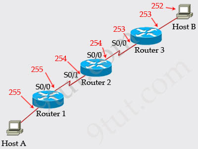
The picture below shows TTL values for each interface of each router and for Host B. Notice that Host A initializes ICMP packet with a TTL of 255:
Here you will find answers to Basic Command Questions
Question 1
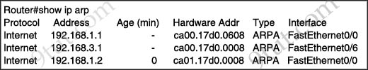
Refer to the exhibit. What can be determined from the output?
Image may be NSFW. Clik here to view.
A. 192.168.1.2 is local to the router.
B. 192.168.3.1 is local to the router.
C. 192.168.1.2 will age out in less than 1 minute.
D. 192.168.3.1 has aged out and is marked for deletion.
Answer: B
Explanation
The “Age” field in the “show ip arp” command is the age in minutes of the cache entry. A hyphen (-) means the address is local so in this case 192.168.1.1 & 192.168.3.1 are local to this router -> B is correct.
Note: The “Age 0″ means that the address was cached less than 1 minute ago.
Question 2
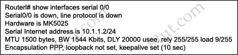
Refer to the exhibit. What could be possible causes for the “Serial0/0 is down” interface status? (Choose two)
Image may be NSFW. Clik here to view.
A. A Layer 1 problem exists.
B. The bandwidth is set too low.
C. A protocol mismatch exists.
D. An incorrect cable is being used.
E. There is an incorrect IP address on the Serial 0/0 interface.
Answer: A D
Explanation
The first part of the “Serial0/0 is down, line protocol is down” indicates a layer 1 problem while the second part indicates a layer 2 problem -> A is correct.
Some popular layer 1 problems are listed below:
+ device power off
+ device power unplugged
+ loose network cable connection
+ incorrect cable type
+ faulty network cable
Answer B “The bandwidth is set too low” will not make a layer 1 problem.
Answer C is a layer 2 problem.
Answer E is a layer 3 problem.
Question 3
Which line from the output of the show ip interface command indicates a layer 1 problem?
A. Serial0/1 is up, line protocol is down
B. Serial0/1 is down, line protocol is down
C. Serial0/1 is up, line protocol is up
D. Serial0/1 is administratively down, line protocol is down
Answer: B
Explanation
Same as question 2.
Question 4
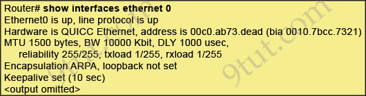
Refer to the exhibit. What is the meaning of the output MTU 1500 bytes?
Image may be NSFW. Clik here to view.
A. The maximum number of bytes that can traverse this interface per second is 1500.
B. The minimum segment size that can traverse this interface is 1500 bytes.
C. The maximum segment size that can traverse this interface is 1500 bytes.
D. The minimum packet size that can traverse this interface is 1500 bytes.
E. The maximum packet size that can traverse this interface is 1500 bytes.
F. The maximum frame size that can traverse this interface is 1500 bytes.
Answer: E
Explanation
The Maximum Transmission Unit (MTU) defines the maximum Layer 3 packet (in bytes) that the layer can pass onwards.
Question 5
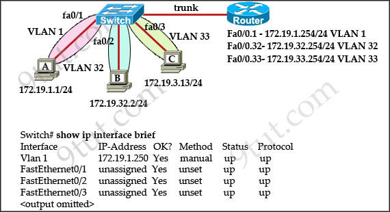
The network administrator normally establishes a Telnet session with the switch from host A. The administrator’s attempt to establish a connect via Telnet to the switch from host B fails, but pings from host B to other two hosts are successful. What is the issue for this problem?
Image may be NSFW. Clik here to view.
A. Host B and the switch need to be in the same subnet.
B. The switch needs an appropriate default gateway assigned.
C. The switch interface connected to the router is down.
D. Host B need to be assigned an IP address in vlan 1.
Answer: B
Explanation
Host A (172.19.1.1) and the management IP address of the Switch (172.19.1.250) are in the same subnet so telnet from host A to the switch can be successful even if a default gateway is not set on host A.
Although the switch has an IP address in Interface Vlan1 but it does not have a default gateway command pointing to the ip address on interface 172.19.1.254 -> B is correct.
Question 6
Which command displays CPU utilization?
A. show protocols
B. show process
C. show system
D. show version
Answer: B
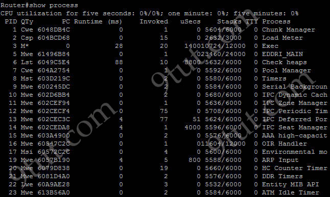
Explanation
The “show process” (in fact, the full command is “show processes”) command gives us lots of information about each process but in fact it is not easy to read. Below shows the output of this command (some next pages are omitted)
Image may be NSFW. Clik here to view.
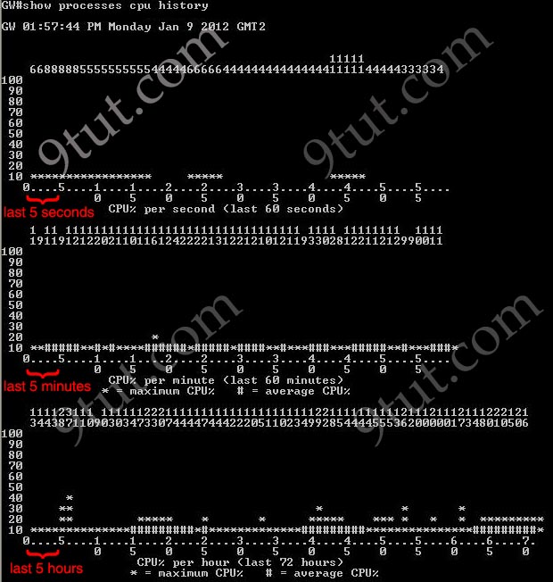
A more friendly way to check the CPU utilization is the command “show processes cpu history”, in which the total CPU usage on the router over a period of time: one minute, one hour, and 72 hours are clearly shown:
Image may be NSFW. Clik here to view.
+ The Y-axis of the graph is the CPU utilization.
+ The X-axis of the graph is the increment within the period displayed in the graph
For example, from the last graph (last 72 hours) we learn that the highest CPU utilization within 72 hours is 37% about six hours ago.
Question 7
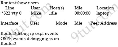
Refer to the exhibit. You are connected to the router as user Mike. Which command allows you to see output from the OSPF debug command?
Image may be NSFW. Clik here to view.
A. terminal monitor
B. show debugging
C. show sessions
D. show ip ospf interface
Answer: A
Explanation
By default, Cisco IOS does not send log messages to a terminal session over IP like Telnet, SSH but console connections do have logging feature enabled by default. To display debug command output and system error messages for Telnet or SSH session, use the “terminal monitor” command in privileged mode.
Here you will find answers to TCP/IP Model & Operation Questions
Question 1
An inbound access list has been configured on a serial interface to deny packet entry for TCP and UDP ports 21, 23 and 25. What types of packets will be permitted by this ACL? (Choose three)
A. FTP
B. Telnet
C. SMTP
D. DNS
E. HTTP
F. POP3
Answer: D E F
Explanation
The access list denies packet entry for TCP & UDP -> all the services on ports 21, 23 and 25 are disabled. Services on these ports are FTP (port 21), Telnet (port 23), SMTP (port 25). Other services are allowed so D E F are the correct answers.
Question 2
What are two characteristics of Telnet? (Choose two)
A. It sends data in clear text format.
B. It is no longer supported on Cisco network devices.
C. It is more secure than SSH.
D. It requires an enterprise license in order to be implemented.
E. It requires that the destination device be configured to support Telnet connections.
Answer: A E
Explanation
Telnet, part of the TCP/IP protocol suite, is a virtual terminal protocol that allows you to make connections to remote devices, gather information, and run programs. Telnet is considered insecure because it transfers all data in clear text -> A is correct.
The destination device needs to support Telnet connection. For example, if a device doesn’t support TCP/IP protocol suit then maybe we can’t telnet to it.
Question 3
An administrator issues the command ping 127.0.0.1 from the command line prompt on a PC. If a reply is received, what does this confirm?
A. The PC has connectivity with a local host.
B. The PC has connectivity with a Layer 3 device.
C. The PC has a default gateway correctly configured
D. The PC has connectivity up to Layer 5 of the OSI model
E. The PC has the TCP/IP protocol stack correctly installed.
Answer: E
Explanation
The address 127.0.0.1 is called loopback address. When we ping 127.0.0.1, in fact we are pinging the local network card and test the TCP/IP protocol suite on our device.
Question 4
Where does routing occur within the DoD TCP/IP reference model?
A. application
B. internet
C. network
D. transport
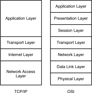
Answer: B
Explanation
The picture below shows the comparison between TCP/IP model & OSI model. Notice that the Internet Layer of TCP/IP is equivalent to the Network Layer which is responsible for routing decision.
Image may be NSFW. Clik here to view.
Question 5
A host is attempting to send data to another host on a different network. What is the first action that the sending host will take?
A. Drop the data.
B. Send the data frames to the default gateway.
C. Create an ARP request to get a MAC address for the receiving host.
D. Send a TCP SYN and wait for the SYN ACK with the IP address of the receiving host.
Answer: B
Explanation
Before sending data, the sending host checks if the destination host is inside or outside the local network. If it is outside the local network, the data will be sent to the default gateway.
Question 6
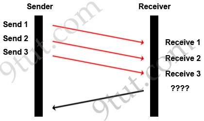
A TCP/IP Transfer is diagrammed in the exhibit.
A window size of three has been negotiated for this transfer. Which message will be returned from the receiver to the sender as part of this TCP/IP transfer?
Image may be NSFW. Clik here to view.
A. Send ACK 1-3
B. Send ACK 3
C. Send ACK 4
D. Send ACK 4-6
E. Send ACK 6
F. Send ACK 7
Answer: C
Explanation
In response, the receiver replies with an ACK. The acknowledgment number is set to one more than the received sequence number. The ACK means “I have got all messages up to sequence number n-1 so please send me the message for sequence number n”.
Question 7
What is the purpose using the traceroute command?
A. to map all the devices on a network.
B. to display the current TCP/IP configuration values.
C. to see how a device MAC address is mapped to its IP address.
D. to see the path a packet will take when traveling to a specified destination.
E. to display the MTU values for each router in a specified network path from source to a destination.
Answer: D
Question 8
A network admin wants to know every hop the packets take when he accesses cisco.com. Which command is the most appropriate to use?
A. path cisco.com
B. debugcisco.com
C. trace cisco.com
D. traceroute cisco.com
Answer: D
Question 9
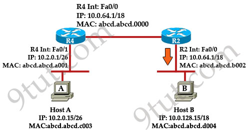
Refer to the exhibit. Host A pings Host B. What source MAC address and source IP address are contained in the frame as the frame leaves R2 destined for host B?
Image may be NSFW. Clik here to view.
A. abcd.abcd.a001
B. abcd.abcd.b002
C. abcd.abcd.c003
D. 10.2.0.15
E. 10.0.64.1
F. 10.0.128.15
Answer: B D
Explanation
When packets are sent from Host A to Host B, the source and destination IP addresses are never changed and they are the IP addresses of Host A & Host B. Only the MAC addresses will be changed to reflect the device of the current network. In this case, when the frame leaves R2 destined for host B. It will have:
+ Source IP: IP of Host A - 10.2.0.15 (never changed)
+ Destination IP: IP of Host B – 10.0.128.15 (never changed)
+ Source MAC: MAC of Fa0/0 of R2 – abcd.abcd.b002
+ Destination MAC: MAC of Host B – abcd.abcd.d004
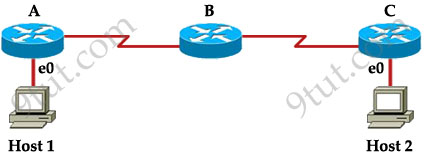
Question 10
Host 1 is trying to communicate with Host 2. The e0 interface on Router C is down. Which of the following are true? (Choose two)
Image may be NSFW. Clik here to view.
A. Router C will use ICMP to inform Host 1 that Host 2 cannot be reached.
B. Router C will use ICMP to inform Router B that Host 2 cannot be reached.
C. Router C will use ICMP to inform Host 1, Router A, and Router B that Host 2 cannot be reached.
D. Router C will send a Destination Unreachable message type.
E. Router C will send a Router Selection message type.
F. Router C will send a Source Quench message type.
Answer: A D
Explanation
The last known good router will try to inform you that the destination cannot be reached (with a Destination Unreachable message type) so from that information you can learn how far your packets can travel to and where the problem is.
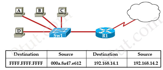
Question 11
Refer to the exhibit. The switch in the graphic has a default configuration and the MAC table is fully populated. In addition, this network is operating properly. The graphic represents selected header information in a frame leaving host A. What can be concluded from this information?
Image may be NSFW. Clik here to view.
A. The MAC address of host A is FFFF.FFFF.FFFF.
B. The router will forward the packet in this frame to the Internet.
C. The switch will only forward this frame to the attached router interface.
D. All devices in this LAN except host A will pass the packet to Layer 3.
Answer: D
Explanation
This frame is leaving host A so host A is the source of this frame. In this frame, the MAC destination is FFFF.FFFF.FFFF which is a broadcast address so Sw1 will flood this frame out all its ports except the port it received the frame -> Hosts B, C, D and the interface connected to Sw1 on R1 will receive this frame. When receiving this frame, they will pass the packet to Layer 3 (because they consider broadcast address “everyone, including me”). At Layer 3, the Destination IP will be checked and only the host (or the interface on the router) with correct IP will respond to Host A while others keep silence -> D is correct.
Just for your information, maybe you can ask “this is a broadcast message so why router R1 doesn’t drop it?”. Suppose this is an ARP Request message. In fact, R1 drops that packet but it also learns that it is an ARP Request so R1 looks up its routing table to find a route to that destination. If it can find one, it will send an ARP Reply back for host A”.
Note: If you are not sure about OSI Model, please read my OSI tutorial.
Question 1
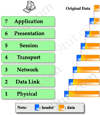
Which of the following correctly describe steps in the OSI data encapsulation process? (Choose two)
A. The transport layer divides a data stream into segments and may add reliability and flow control information.
B. The data link layer adds physical source and destination addresses and an FCS to the segment.
C. Packets are created when the network layer encapsulates a frame with source and destination host addresses and protocol-related control information.
D. Packets are created when the network layer adds Layer 3 addresses and control information to a segment.
E. The presentation layer translates bits into voltages for transmission across the physical link.
Answer: A D
Explanation
The transport layer segments data into smaller pieces for transport. Each segment is assigned a sequence number, so that the receiving device can reassemble the data on arrival.
The transport layer also use flow control to maximize the transfer rate while minimizing the requirements to retransmit. For example, in TCP, basic flow control is implemented by acknowledgment by the receiver of the receipt of data; the sender waits for this acknowledgment before sending the next part.
-> A is correct.
The data link layer adds physical source and destination addresses and an Frame Check Sequence (FCS) to the packet (on Layer 3), not segment (on Layer 4) -> B is not correct.
Packets are created when network layer encapsulates a segment (not frame) with source and destination host addresses and protocol-related control information. Notice that the network layer encapsulates messages received from higher layers by placing them into datagrams (also called packets) with a network layer header -> C is not correct.
The Network layer (Layer 3) has two key responsibilities. First, this layer controls the logical addressing of devices. Second, the network layer determines the best path to a particular destination network, and routes the data appropriately.
-> D is correct.
The Physical layer (not presentation layer) translates bits into voltages for transmission across the physical link -> E is not correct.
Question 2
Which layer of the OSI reference model uses the hardware address of a device to ensure message delivery to the proper host on a LAN?
A. physical
B. data link
C. network
D. transport
Answer: B
Explanation
The hardware address of a device or the Media Access Control (MAC) address is added in the Data Link layer. An Ethernet MAC address is a 48-bit binary value expressed as 12 hexadecimal digits (for example: 00:15:A4:CB:03:CA).
Question 3
Which layer of the OSI reference model uses flow control, sequencing, and acknowledgments to ensure that reliable networking occurs?
A. data link
B. network
C. transport
D. presentation
E. physical
Answer: C
Question 4
Which layer in the OSI reference model is responsible for determining the availability of the receiving program and checking to see if enough resources exist for that communication?
A. transport
B. network
C. presentation
D. session
E. application
Answer: E
Question 5
Data transfer is slow between the source and destination. The quality of service requested by the transport layer in the OSI reference model is not being maintained. To fix this issue, at which layer should the troubleshooting process begin?
A. presentation
B. session
C. transport
D. network
E. physical
Answer: D
Question 6
Which protocols are found in the network layer of the OSI reference model and are responsible for path determination and traffic switching?
A. LAN
B. routing
C. WAN
D. network
Answer: B
Question 7
Refer to the exhibit. An administrator pings the default gateway at 10.10.10.1 and sees the output as shown. At which OSI layer is the problem?
C:\> ping 10.10.10.1
Pinging 10.10.10.1 with 32 bytes of data:
Request timed out.
Request timed out.
Request timed out.
Request timed out.
Ping statistics for 10.10.10.1:
Packets: sent – 4, Received = 0, Lost – 4 (100% loss)
A. data link layer
B. application layer
C. access layer
D. session layer
E. network layer
Answer: E
Explanation
The Network layer is responsible for network addressing and routing through the internetwork. So a ping fails, you may have an issue with the Network layer (although lower layers like Data Link & Physical may cause the problem).
Question 8
Which of the following are types of flow control? (Choose three)
A. buffering
B. cut-through
C. windowing
D. congestion avoidance
E. load balancing
Answer: A C D
Explanation
Three types of flow control are buffering, windowing & congestion avoidance:
+ Buffering: If a device receives packets too quickly for it to handle then it can store them in a memory section called a buffer and proceed them later.
+ Windowing: a window is the quantity of data segments that the transmitting device is allowed to send without receiving an acknowledgment for them. For example:
With the window size of 1, the sending device sends 1 segment and the receiving device must reply with 1 ACK before the sending device can send the next segment. This “waiting” takes some time.
By increasing the window size to 3, the sending device will send up to 3 segments before waiting an ACK -> helps reduce the waiting time.
+ Congestion avoidance: lower-priority traffic can be discarded when the network is overloaded -> minimize delays.
Question 9
A network administrator is verifying the configuration of a newly installed host by establishing an FTP connection to a remote server. What is the highest layer of the protocol stack that the network administrator is using for this operation?
A. application
B. presentation
C. session
D. transport
E. internet
F. data link
Answer: A
Explanation
FTP belongs to Application layer and it is also the highest layer of the OSI model.
Question 10
A receiving host computes the checksum on a frame and determines that the frame is damaged. The frame is then discarded. At which OSI layer did this happen?
A. session
B. network
C. physical
D. data link
E. transport
Answer: D
Explanation
When using the term “frame” we can easily recognize it belongs to the Data Link layer. In this layer, an Frame Check Sequence (FCS) field is added to the frame to verify that the frame data is received correctly.
Question 11
As a frame leaves a Layer 3 device, the Layer 2 encapsulation information is changed from what it was when it entered the device. For what two reasons can this happen? (Choose two)
A. The data is moving from 10BASE-TX to 100BASE-TX.
B. The WAN encapsulation type has changed.
C. The data format has changed from analog to digital.
D. The source and destination hosts are in the same subnet.
E. The source and destination MAC addresses have changed.
Answer: B E
Question 12
Acknowledgement, Sequencing, and Flow control are characteristics of which OSI layer?
A. Layer 2
B. Layer 3
C. Layer 4
D. Layer 5
E. Layer 6
F. Layer 7
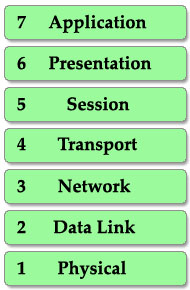
Welcome to the most basic tutorial for networker! Understanding about OSI model is one of the most important tools to help you grasp how networking devices like router, switch, PC… work.
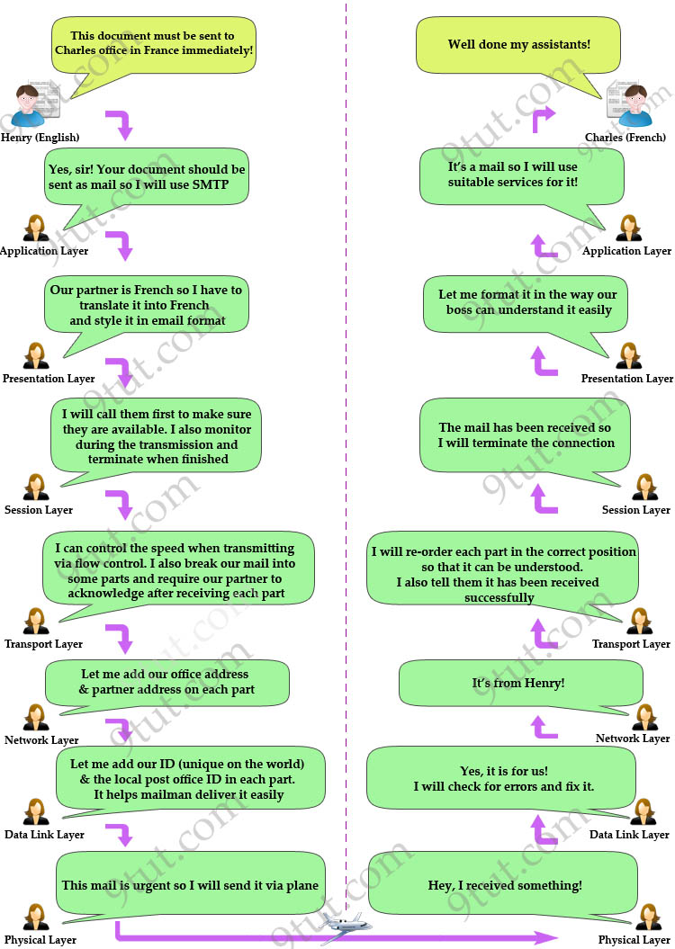
Let’s take an example in our real life to demonstrate the OSI model. Maybe you have ever sent a mail to your friend, right? To do it, you have to follow these steps:
1. Write your letter
2. Insert it into an envelope
3. Write information about sender and receiver on that envelope
4. Stamp it
5. Go to the post office and drop it into a mail inbox
From the example above, I want to imply we have to go through some steps in a specific order to complete a task. It is also applied for two PCs to communicate with each other. They have to use a predefined model, named OSI, to complete each step. There are 7 steps in this model as listed below:
Image may be NSFW. Clik here to view.
This is also the well-known table of the OSI model so you must take time to learn by heart. A popular way to remember this table is to create a fun sentence with the first letters of each layer. For example: All People Seem To Need Data Processing or a more funny sentence sorted from layer 1 to layer 7: Please Do Not Throw Sausage Pizza Away.
There are two notices about this table:
1. First, the table is arranged from top to bottom (numbering from 7 to 1). Each step is called a “layer” so we have 7 layers (maybe we usually call them “layers” to make them more… technical ^^).
When a device wants to send information to another one, its data must go from top to bottom layer. But when a device receives this information, it must go from bottom to top to “decapsulate” it. In fact, the reverse action at the other end is very natural in our life. It is very similar when two people communicate via mail. First, the writer must write the letter, insert it into an envelope while the receiver must first open the envelope and then read the mail. The picture below shows the whole process of sending and receiving information.
Image may be NSFW. Clik here to view.
Note: The OSI model layers are often referred to by number than by name (for example, we refer saying “layer 3″ to “network layer”) so you should learn the number of each layer as well.
2. When the information goes down through layers (from top to bottom), a header is added to it. This is called encapsulation because it is like wrapping an object in a capsule. Each header can be understood only by the corresponding layer at the receiving side. Other layers only see that layer’s header as a part of data.
Image may be NSFW. Clik here to view.
At the receiving side, corresponding header is stripped off in the same layer it was attached.
Understand each layer
Layer 7 – Application layer
This is the closest layer to the end user. It provides the interface between the applications we use and the underlying layers. But notice that the programs you are using (like a web browser – IE, Firefox or Opera…) do not belong to Application layer. Telnet, FTP, email client (SMTP), HyperText Transfer Protocol (HTTP) are examples of Application layer.
Layer 6 – Presentation layer
This layer ensures the presentation of data, that the communications passing through are in the appropriate form for the recipient. In general, it acts as a translator of the network. For example, you want to send an email and the Presentation will format your data into email format. Or you want to send photos to your friend, the Presentation layer will format your data into GIF, JPG or PNG… format.
Layer 5 – Session layer
Layer 5 establishes, maintains and ends communication with the receiving device.
Layer 4 – Transport layer
This layer maintains flow control of data and provides for error checking and recovery of data between the devices. The most common example of Transport layer is Transmission Control Protocol (TCP) and User Datagram Protocol (UDP).
Layer 3 – Network layer
This layer provides logical addresses which routers will use to determine the path to the destination. In most cases, the logic addresses here means the IP addresses (including source & destination IP addresses).
Layer 2 – Data Link Layer
The Data Link layer formats the message into a data frame, and adds a header containing the hardware destination and source address to it. This header is responsible for finding the next destination device on a local network.
Notice that layer 3 is responsible for finding the path to the last destination (network) but it doesn’t care about who will be the next receiver. It is the Layer 2 that helps data to reach the next destination.
This layer is subdivide into 2 sub-layers: logical link control (LLC) and media access control (MAC).
The LLC functions include:
+ Managing frames to upper and lower layers
+ Error Control
+ Flow control
The MAC sublayer carries the physical address of each device on the network. This address is more commonly called a device’s MAC address. MAC address is a 48 bits address which is burned into the NIC card on the device by its manufacturer.
Layer 1 – Physical layer
The Physical Layer defines the physical characteristics of the network such as connections, voltage levels and timing.
To help you remember the functions of each layer more easily, I created a fun story in which Henry (English) wants to send a document to Charles (French) to demonstrate how the OSI model works.
Image may be NSFW. Clik here to view.
Lastly, I summarize all the important functions of each layer in the table below (please remember them, they are very important knowledge you need to know about OSI model):
Includes 2 layers:
+ Upper layer: Logical Link Control (LLC)
+ Lower layer: Media Access Control (MAC)
+ LAN
+ WAN (HDLC, PPP, Frame Relay…)
Frame
Switch, Bridge
Physical
Encodes and transmits data bits
+ Electric signals
+ Radio signals
+ FDDI, Ethernet
Bit (0, 1)
Hub, Repeater…
Note: In fact, OSI is just is a theoretical model of networking. The practical model used in modern networks is the TCP/IP model. You may think “Hm, it’s just theoretic and has no use in real life! I don’t care!” but believe me, you will use this model more often than the TCP/IP model so take time to grasp it, you will not regret – I promise :)
Refer to the exhibit. A router boots to the prompt shown in the exhibit. What does this signify, and how should the network administrator respond?
rommon 1>
A. This prompt signifies that the configuration file was not found in NVRAM. The network administrator should follow the prompts to enter a basic configuration.
B. The prompt signifies that the configuration file was not found in flash memory. The network administrator should use TFTP to transfer a configuration file to the router.
C. The prompt signifies that the IOS image in flash memory is invalid or corrupted. The network administrator should use TFTP to transfer an IOS image to the router.
D. The prompt signifies that the router could not authenticate the user. The network administrator should modify the IOS image and reboot the router.
Answer: C
Explanation
If a Cisco router boots in ROMmon mode, it means:
+ The value of the configuration register is set to XXX0 (the boot field – fourth bit – is 0)
+ The router is unable to locate a valid Cisco IOS software image (you can use the “dir flash:” command in ROMmon mode to look for the IOS in the Flash then try to boot that flash with the “boot flash:” command).
If the IOS image is invalid or corrupted, the fastest way to re-install a new Cisco IOS software image on the router is to copy a new one from TFTP (with “tftpdnld” command).
Question 2
What should be done prior to backing up an IOS image to a TFTP server? (Choose three)
A. Make sure that the server can be reached across the network.
B. Check that authentication for TFTP access to the server is set.
C. Assure that the network server has adequate space for the IOS image.
D. Verify file naming and path requirements.
E. Make sure that the server can store binary files.
F. Adjust the TCP window size to speed up the transfer.
Answer: A C D
Question 3
Which two privileged mode cisco ios commands can be used to determine a cisco router chassis serial number? (choose two)
A. show inventory
B. show flash filesys
C. dir flash:|include chassis
D. show diag
E. show controllers
Answer: A D
Question 4
Which command helps a network administrator to manage memory by displaying flash memory and NVRAM utilization?
A. show secure
B. show file systems
C. show flash
D. show version
Answer: B
Question 5
A network administrator changes the configuration register to 0×2142 and reboots the router. What are two results of making this change? (Choose two)
A. The IOS image will be ignored.
B. The router will prompt to enter initial configuration mode.
C. The router will boot to ROM.
D. Any configuration entries in NVRAM will be ignored.
E. The configuration in flash memory will be booted.
Answer: B D
Explanation
The router bypasses the startup configuration stored in NVRAM during its boot sequence so the router will enter initial configuration mode. This feature is normally used during a password recovery procedure.
Question 6
Refer to the exhibit. For what two reasons has the router loaded its IOS image from the location that is shown? (Choose two)
Router1> show version
Cisco Internetwork Operating System Software
IOS ™ 7200 Software (C7200-J-M), Experimental Version 11.3tl997091S:1647S2)
[hampton-nitro-baseline 249]
Copyright (c) 1986-1997 by cisco Systems, Inc.
Compiled Wed 08-0ct-97 06:39 by hampton
Image text-base: 0×60008900, data-base: 0x60B98000
ROM: System Bootstrap, Version 11.1(11855) [beta 2], INTERIM SOFTWARE
BOOTPLASH: 7200 Software (C7200-BOOT-M), Version 11.1(472), RELEASE SOFTWARE (fcl)
Router1 uptime is 23 hours, 33 minutes
System restarted by abort at PC 0x6022322C at 10:50:SS PDT Tue Oct 21 1997
System image file is “tftp://112.16.1.129/hampton/nitro/c7200-j-mz”
cisco 7206 (NPE150) processor with 57344K/8192K bytes of memory.
Configuration register is 0×2102
A. Router1 has specific boot system command that instruct it to load IOS from TFTP server.
B. Router1 is acting as a TFTP server for other routers.
C. Router1 cannot locate a valid IOS image in flash memory.
D. Router1 defaulted to ROMMON mode and loaded the IOS image from a TFTP sewer.
E. Cisco routers will first attempt to load a image from TFTP for management purposes.
Answer: A C
Explanation
When powered on, the router first checks its hardware via Power-On Self Test (POST). Then it checks the configuration register to identify where to load the IOS image from. In the output above we learn that the Configuration register value is 0×2102 so the router will try to boot the system image from Flash memory first.
But we also see a line “System image file is “tftp://112.16.1.129/hampton/nitro/c7200-j-mz”. Please notice that this line tells us the image file that the device last started. In this case it is from a TFTP server. Therefore we can deduce that the router could not load the IOS image from the flash and the IOS image has been loaded from TFTP server.
Note:
If the startup-config file is missing or does not specify a location, it will check the following locations for the IOS image:
+ Flash (the default location)
+ TFTP server
+ ROM (used if no other source is found)
When you are logged into a switch, which prompt indicates that you are in privileged mode?
A. %
B. @
C. >
D. $
E. #
Answer: E
Explanation
The “#” (like Switch#) indicates you are in privileged mode while the “>” indicates you are in user mode.
Note: The “#” sign in “Switch(config)#” indicates this is only accessible at privileged EXEC mode. The “(config)#” part indicates we are in configuration mode.
Below lists popular modes in Cisco switch/router:
Router>
User EXEC mode
Router#
Privileged EXEC mode
Router(config)#
Configuration mode
Router(config-if)#
Interface level (within configuration mode)
Router(config-router)#
Routing engine level (within configuration mode)
Router(config-line)#
Line level (vty, tty, async) within configuration mode
Question 2
Which command is used to copy the configuration from RAM into NVRAM?
A. copy running-config startup-config
B. copy startup-config: running-config:
C. copy running config startup config
D. copy startup config running config
E. write terminal
Answer: A
Explanation
The running-config is saved in RAM while the startup-config is saved in NVRAM. So in order to copy the configuration from RAM into NVRAM we use the command “copy running-config startup-config” (syntax: copy).
Question 3
Which command is used to load a configuration from a TFTP server and merge the configuration into RAM?
A. copy running-config: TFTP:
B. copy TFTP: running-config
C. copy TFTP: startup-config
D. copy startup-config: TFTP:
Answer: B
Explanation
The syntax of the copy command is “copy” so to copy a configuration from a TFTP server into RAM we use the command “copy TFTP: running-config”.
Question 4
There are no boot system commands in a router configuration in NVRAM. What is the fallback sequence that router will use to find an IOS during reload?
A. Flash, TFTP server, ROM
B. Flash, NVRAM, ROM
C. ROM, NVRAM, TFTP server
D. NVRAM, TFTP server, ROM
E. TFTP server, Flash, NVRAM
Answer: A
Explanation
When you turn the router on, it runs through the following boot process.
The Power-On Self Test (POST) checks the router’s hardware. When the POST completes successfully, the System OK LED indicator comes on.
The router checks the configuration register to identify where to load the IOS image from. A setting of 0×2102 means that the router will use information in the startup-config file to locate the IOS image. If the startup-config file is missing or does not specify a location, it will check the following locations for the IOS image:
1. Flash (the default location)
2. TFTP server
3. ROM (used if no other source is found)
The router loads the configuration file into RAM (which configures the router). The router can load a configuration file from:
+ NVRAM (startup-configuration file)
+ TFTP server
If a configuration file is not found, the router starts in setup mode.
Question 5
A Cisco router is booting and has just completed the POST process.It is now ready to find and load an IOS image. What function does the router perform next?
A. It checks the configuration register
B. It attempts to boot from a TFTP server
C. It loads the first image file in flash memory
D. It inspects the configuration file in NVRAM for boot instructions
Answer: A
Explanation
Same as Question 4
Question 6
Refer to the partial command output shown. Which two statements are correct regarding the router hardware? (Choose two)
system image file is “flash:c2600-do3s-mz.120-5.T1″
Cisco 2621 (MPC860) processor (revision 0×600) with 53248K/12288K bytes of memory
Processor board ID JAD05280307 (3536592999)
M860 processor: part number 0, mask 49
Bridging software.
X.25 software, version 3.0.0.
2 FastEthernet/IEEE 802.3 interface(s)
2 Serial(sync/async) network interface(s)
2 Low-speed serial(sync/async) network interface(s)
16 terminal line(s)
32K bytes of non-volatile configuration memory.
16384K bytes of processor board system flash (Read/Write)
A. Total RAM size is 32 KB
B. Total RAM size is 16384 KB (16 MB)
C. Total RAM size is 65536 KB (64 MB)
D. Flash size is 32 KB
E. Flash size is 16384 KB (16 MB).
F. Flash size is 65536 KB (64 MB)
Answer: C E
Explanation
The line “Cisco 2621 (MPC860) processor (revision 0×600) with 53248K/12288K bytes of memory” tells how much RAM in your router. The first parameter (53248) specifies how much Dynamic RAM (DRAM) in your router while the second parameter (12288K) indicates how much DRAM is being used for Packet memory (used by incoming and outgoing packets) in your router. Therefore you have to add both numbers to find the amount of DRAM available on your router -> C is correct.
Note: Cisco 4000, 4500, 4700, and 7500 routers have separate DRAM and Packet memory, so you only need to look at the first number to find out the DRAM in that router.
The flash size is straightforward from the line “16384K bytes of processor board system flash (Read/Write)” -> E is correct.
Which router IOS commands can be used to troubleshoot LAN connectivity problems? (Choose three)
A. ping
B. tracert
C. ipconfig
D. show ip route
E. winipcfg
F. show interfaces
Answer: A D F
Explanation
The ping command can be used to test if the local device can reach a specific destination -> A is correct.
“tracert” is not a valid command in Cisco IOS commands, the correct command should be “traceroute” -> B is not correct.
The ipconfig command is not a valid command in Cisco IOS too -> C is not correct.
The “show ip route” command can be used to view the routing table of the router. It is a very useful command to find out many connectivity problems (like directly connected networks, learned network via routing protocols…) -> D is correct.
“winipcfg” is an old tool in Windows 95/98 to view IP settings of the installed network interfaces. But it is not a valid command in Cisco IOS commands -> E is not correct.
The “show interfaces” command is used to check all the interfaces on the local device only. It has very limited information to trouble LAN connectivity problem but it is the most reasonable to choose -> F is acceptable.
Question 8
Which two locations can be configured as a source for the IOS image in the boot system command? (Choose two)
A. RAM
B. NVRAM
C. flash memory
D. HTTP server
E. TFTP server
F. Telnet server
Answer: C E
Explanation
The following locations can be configured as a source for the IOS image:
+ Flash (the default location)
+ TFTP server
+ ROM (used if no other source is found)
(Please read the explanation of Question 4 for more information)
Question 9
Refer to the exhibit. Why is flash memory erased prior to upgrading the IOS image from the TFTP server?
Router# copy tftp flash
Address or name of remote host []? 192.168.2.167
Source filename []? c1600-k8sy-mz.123-16a.bin
Destination filename [c1600-k8sy-mz.123-16a.bin]?
Accessing tftp://192.168.2.167/ c1600-k8sy-mz.l23-16a.bin…
Erasing flash before copying? [confirm]
Erasing the flash filesystem will remove all files! continue? [confirm]
Erasing device
Eeeeeeeeeeeeeeeeeeeeeeeeeeeeeeeeeeeeeeeeeeeeeeeeeeeeeeeeeeeeeeeeeeeeeeeee
Eeeeeeeeeeeeeeeeeeeeeeeeeeeeeee …erased
Erase of flash: complete
Loading c1600-k8sy-mz.l23-16a.bin from 192.168.2.167 (via Ethernet0):
!!!!!!!!!!!!!!!!!!!!!!!!!!!!!!!!!!!!!!!!!!!!!!!!!!!!!!!!!!!!!!!!!!!!!!!!!!!!!!!!!!!!!!!!!!!!!!!!!!!!!!!!!!!!
!!!!!!!!!!!!!!!!!!!!!!!!!!!!!!!!!!!!!!!!!!!!!!!!!!!!!!!!!!!!!!!!!!!!!!!!!!!!!!!!!!!!!!!!!!!!!!!!!!!!!!!!!!!!
!!!!!!!!!!!!!!!!!!!!!!!!!!!!!!!!!
[OK - 6888962/13777920 bytes]
verifying checksum… OK (0x7BF3)
6888962 bytes copied in 209.920 secs (32961 bytes/sec)
Router#
A. The router cannot verify that the Cisco IOS image currently in flash is valid
B. Flash memory on Cisco routers can contain only a single IOS image.
C. Erasing current flash content is requested during the copy dialog.
D. In order for the router to use the new image as the default, it must be the only IOS image in flash.
Answer: C
Explanation
During the copy process, the router asked “Erasing flash before copying? [confirm]” and the administrator confirmed (by pressing Enter) so the flash was deleted.
Note: In this case, the flash has enough space to copy a new IOS without deleting the current one. The current IOS is deleted just because the administrator wants to do so. If the flash does not have enough space you will see an error message like this:
%Error copying tftp://192.168.2.167/ c1600-k8sy-mz.l23-16a.bin (Not enough space on device)
Question 10
Which command reveals the last method used to powercycle a router?
A. show reload
B. show boot
C. show running-config
D. show version
Answer: D
Explanation
The “show version” command can be used to show the last method to powercycle (reset) a router
How does using the service password encryption command on a router provide additional security?
A. by encrypting all passwords passing through the router
B. by encrypting passwords in the plain text configuration file
C. by requiring entry of encrypted passwords for access to the device
D. by configuring an MD5 encrypted key to be used by routing protocols to validate routing exchanges
E. by automatically suggesting encrypted passwords for use in configuring the router
Answer: B
Explanation
By using this command, all the (current and future) passwords are encrypted. This command is primarily useful for keeping unauthorized individuals from viewing your password in your configuration file.
Question 2
Refer to the diagram. What is the largest configuration file that can be stored on this router?
R# show version
Cisco IOS Software. 1841 Software (C1841-IPBASE-M}, Version 12.4(1a), RELEASE SOFTWARE (fc2)
Technical Support: http://www.cisco.com/techsupport
Copyright (c) 1986*2005 by Cisco Systems, Inc.
Compiled Fri 27-May-0512:32 by hqluong
ROM: System Bootstrap. Version 12.3(8r)T8, RELEASE SOFTWARE (fc1)
N-East uptime is 5 days, 49 minutes
System returned to ROM by reload at 15:17:00 UTC Thu Jun 8 2006
System image file is “flash:c1841-ipbase-mz.124-1a.bin”
Cisco 1841 (revision 5.0) with 114688K/16384K bytes of memory.
Processor board ID FTX0932W21Y
2 FastEthernet interfaces
2 Low-speed serial(sync/async) interfaces
DRAM configuration is 64 bits wide with parity disabled.
191K bytes of NVRAM.
31360K bytes of ATA CompactFlash (Read/Write)
Configuration register Is 0×2102
R#
A. 191K bytes
B. 16384K bytes
C. 31369K bytes
D. 114688K bytes
Answer: A
Explanation
Non-volatile RAM (NVRAM) holds the router’s startup configuration file. NVRAM contents are not lost when the router is powered down or reloaded.
Question 3
Which command shows system hardware and software version information?
A. show configuration
B. show environment
C. show inventory
D. show platform
E. show version
Answer: E
Question 4
Refer to the exhibit. If number 2 is selected from the setup script, what happens when the user runs setup from a privileged prompt?
[0] Go to the IOS command prompt without saving this config.
[1] Return back to the setup without saving this config.
[2] Save this configuration to nvram and exit.
Enter your selection [2]:
A. Setup is additive and any changes will be added to the config script.
B. Setup effectively starts the configuration over as if the router was booted for the first time.
C. Setup will not run if an enable secret password exists on the router.
D. Setup will not run, because it is only viable when no configuration exists on the router.
Answer: A
Question 5
Which command shows your active Telnet connections?
A. show sessions
B. show cdp neighbors
C. show users
D. show queue
Answer: A
Explanation
The “show users” shows telnet/ssh connections to your router while “show sessions” shows telnet/ssh connections from your router (to other devices). The question asks about “your active Telnet connections”, meaning connections from your router so the answer should be A.
Question 6
Which command can you use to determine the cisco ios feature set on a cisco router?
A. show version
B. dir flash:include ios
C. show environment
D. show diag
E. show inventory
Answer: A
Question 7
A system administrator types the command to change the hostname of a router. Where on the Cisco IFS is that change stored?
A. NVRAM
B. RAM
C. FLASH
D. ROM
E. PCMCIA
Answer: B
Explanation
The change is only reflected in the running-config on RAM. It can be lost if we reset the router without saving it.
Note: Cisco IFS means “Cisco IOS File System”
Question 8
Before installing a new upgraded version of the IOS, what should be checked on the router, and which command should be used to gather this information? (Choose two)
A. the amount of available ROM
B. the amount of available flash and RAM memory
C. the version of the bootstrap software present on the router
D. show version
E. show processes
F. show running-config
Answer: B D
Explanation
When upgrading new version of the IOS we need to copy the IOS to the Flash so first we have to check if the Flash has enough memory or not. Also running the new IOS may require more RAM than the older one so we should check the available RAM too. We can check both with the “show version” command.
Question 9
Refer to the exhibit. A network administrator configures a new router and enters the copy startup-config running-config on the router. The network administrator powers down the router and sets it up at a remote location. When the router starts, it enter the system configuration dialog as shown. What is the cause of the problem?
— System Configuration Dialog —
Would you like to enter the initial configuration dialog? [yes/no]: % Please answer yes’ or ‘no’.
Would you like to enter the initial configuration dialog? [yes/ho]: n
Would you like to terminate autoinstall? [yes]:
Press RETURN to get started!
A. The network administrator failed to save the configuration.
B. The configuration register is set to 0×2100.
C. The boot system flash command is missing from the configuration.
D. The configuration register is set to 0×2102.
E. The router is configured with the boot system startup command.
Answer: A
Explanation
The “System Configuration Dialog” appears only when no startup configuration file is found. The network administrator has made a mistake because the command “copy startup-config running-config” will copy the startup config (which is empty) over the running config (which is configured by the administrator). So everything configured was deleted.
Note: We can tell the router to ignore the start-up configuration on the next reload by setting the register to 0×2142. This will make the “System Configuration Dialog” appear at the next reload.
Question 10
Refer to the exhibit. What can be determined about the router from the console output?
1 FastEthernet/IEEE 802.3 interface(s)
125K bytes of non-volatile configuration memory.
65536K bytes of ATA PCMCIA card at slot 0 (Sector size 512 bytes) .
8192K bytes of Flash internal SIMM (Sector size 256K).
———-System Configuration Dialog ———-
Would you like to enter the initial configuration dialog? [yes/no]:
A. No configuration file was found in NVRAM.
B. No configuration file was found in flash.
C. No configuration file was found in the PCMCIA card.
D. Configuration file is normal and will load in 15 seconds.
Answer: A
Explanation
When no startup configuration file is found in NVRAM, the System Configuration Dialog will appear to ask if we want to enter the initial configuration dialog or not.